Hostcontrol
GPIO13
DSP control
GPIO12
1
2 3 4 65
www.ti.com
Bootloader Features
199
SPRUI07–March 2020
Submit Documentation Feedback
Copyright © 2020, Texas Instruments Incorporated
Boot ROM
Table 2-12. XINTF Parallel Boot 8-Bit Data Stream
Bytes XD[7:0]
(Byte 1 of 2)
XD[7:0]
(Byte 2 of 2)
Description
1 2 AA 08 0x08AA (KeyValue for memory width = 8bits)
3 4 BB AA PLLCR register = 0xAABB
5 6 0B 00 PLLSTS[DIVSEL] bits = 0xB
7 8 BB AA XTIMING6[31:16]
9 10 DD CC XTIMING6[15:0] (XTIMING6 = 0xAABBCCDD)
11 12 FF EE XINTCNF2[31:16]
13 14 HH GG XINTCNF2[15:0] (XINTCNF2 = 0xEEFFGGHH)
15 16 00 00 reserved
17 18 00 00 reserved
19 20 BB 00 Entry point PC[22:16]
21 22 DD CC Entry point PC[15:0] (PC = 0x00BBCCDD)
23 24 NN MM Block size of the first block of data to load = 0xMMNN words
25 26 BB AA Destination address of first block Addr[31:16]
27 28 DD CC Destination address of first block Addr[15:0] (Addr = 0xAABBCCDD)
29 30 BB AA First word of the first block in the source being loaded = 0xAABB
...
...
...
Data for this section.
...
. BB AA Last word of the first block of the source being loaded = 0xAABB
. NN MM Block size of the 2nd block to load = 0xMMNN words
. BB AA Destination address of second block Addr[31:16]
. DD CC Destination address of second block Addr[15:0]
. BB AA First word of the second block in the source being loaded
. …
n n+1 BB AA Last word of the last block of the source being loaded
(More sections if required)
n+2 n+3 00 00 Block size of 0000h - indicates end of the source program
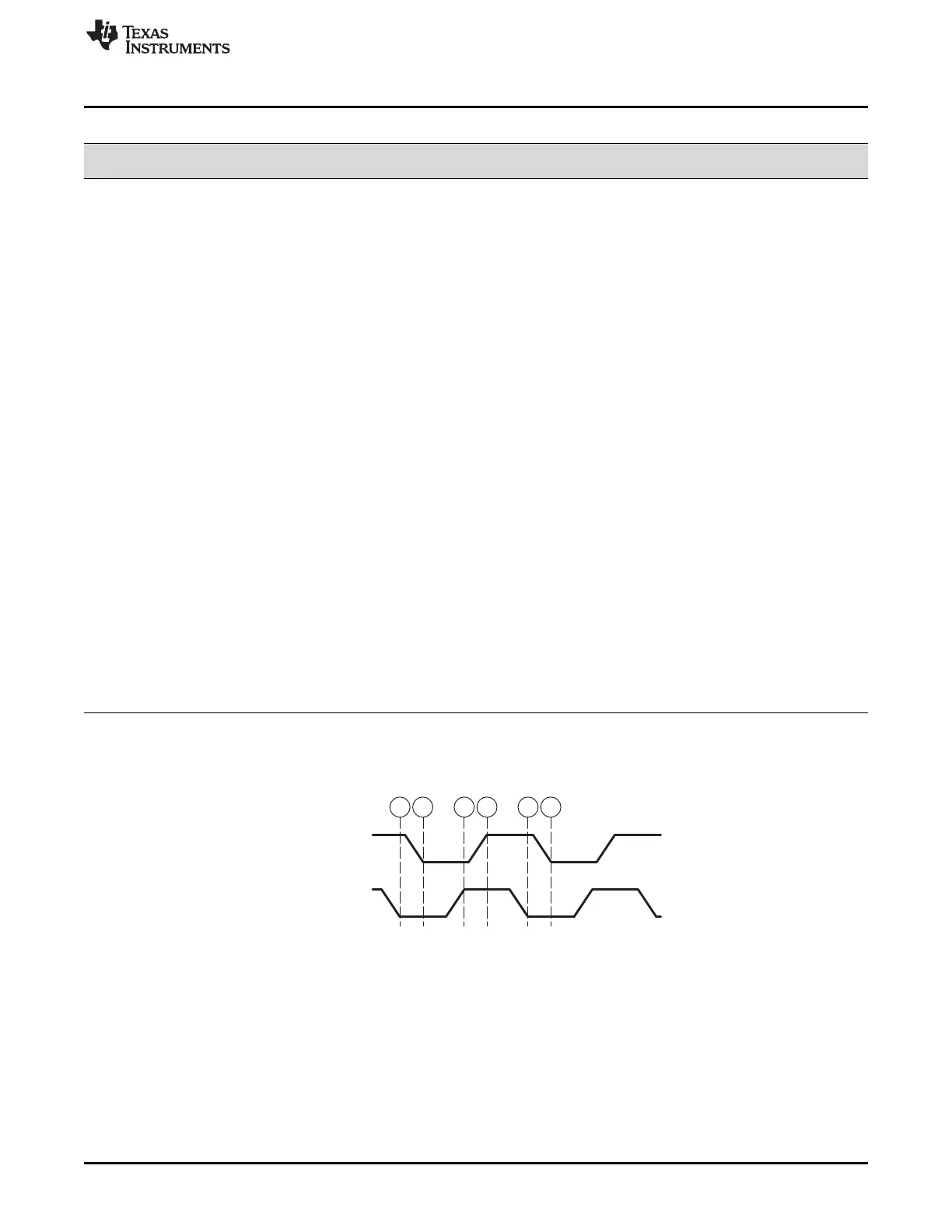
Figure 2-25 shows an overview of the XINTF parallel boot loader handshake protocol.
Figure 2-25. XINTF_Parallel Boot Loader Handshake Protocol
1. The 28x device indicates it is ready to start receiving data by pulling the GPIO12 pin low.
2. The bootloader waits until the host puts data on XD[15:0]. The host signals to the 28x device that data
is ready by pulling the GPIO13 pin low.
3. The 28x device reads the data and signals the host that the read is complete by pulling GPIO12 high.
4. The bootloader waits until the host acknowledges the 28x by pulling GPIO13 high.
5. The 28x device again indicates it is ready for more data by pulling the GPIO12 pin low.
This process is repeated for each data value to be sent.
Figure 2-26 shows an overview of the XINTF parallel bootloader flow.
 Loading...