www.ti.com
I2C Registers
645
SPRUI07–March 2020
Submit Documentation Feedback
Copyright © 2020, Texas Instruments Incorporated
Inter-Integrated Circuit Module (I2C)
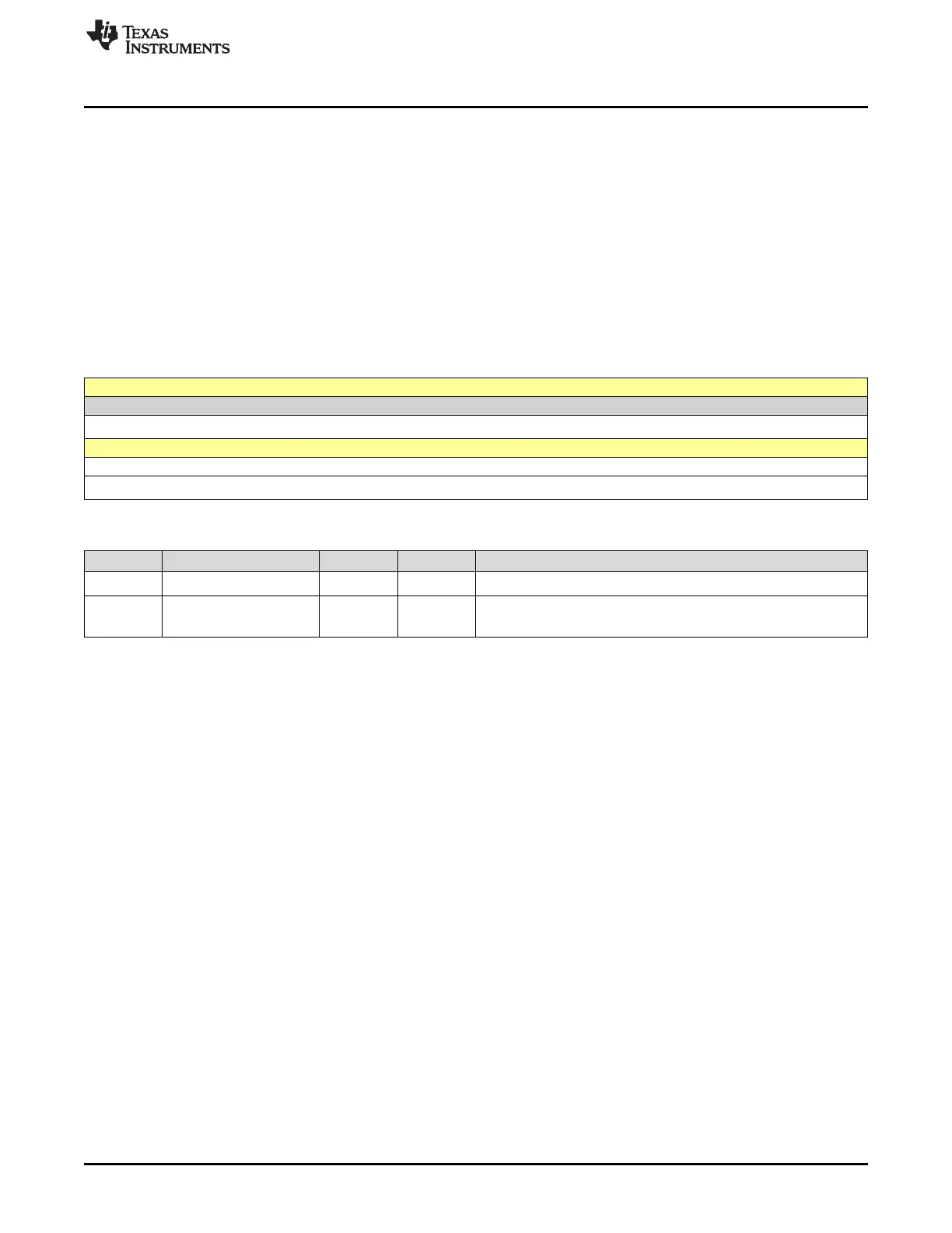
11.6.2.9 I2CDXR Register (Offset = 8h) [reset = 0h]
I2CDXR is shown in Figure 11-26 and described in Table 11-18.
Return to the Summary Table.
The CPU writes transmit data to I2CDXR. This 16-bit register accepts a data byte with 1 to 8 bits. Before
writing to I2CDXR, specify how many bits are in a data byte by loading the appropriate value into the bit
count (BC) bits of I2CMDR. When writing a data byte with fewer than 8 bits, make sure the value is right-
aligned in I2CDXR.
After a data byte is written to I2CDXR, the I2C module copies the data byte to the transmit shift register
(I2CXSR). The CPU cannot access I2CXSR directly. From I2CXSR, the I2C module shifts the data byte
out on the SDA pin, one bit at a time.
When in the transmit FIFO mode, the I2CDXR register acts as the transmit FIFO buffer.
Figure 11-26. I2CDXR Register
15 14 13 12 11 10 9 8
RESERVED
R-0h
7 6 5 4 3 2 1 0
DATA
R/W-0h
Table 11-18. I2CDXR Register Field Descriptions
Bit Field Type Reset Description
15-8 RESERVED R 0h
Reserved
7-0 DATA R/W 0h
Transmit data
Reset type: SYSRSn
 Loading...