S
Variable-width
acquisition window
Clock
SOC
ADC Clock
Channel
Select
SH Clock
ADC SOC
Trigger
S
C2
C1
S
OFF
(B)
C2
[C0NV##] [C0NV##]
(A) (A)
[C0NV##+1]
(A)
C1
www.ti.com
ADC Interface
467
SPRUI07–March 2020
Submit Documentation Feedback
Copyright © 2020, Texas Instruments Incorporated
Analog-to-Digital Converter (ADC)
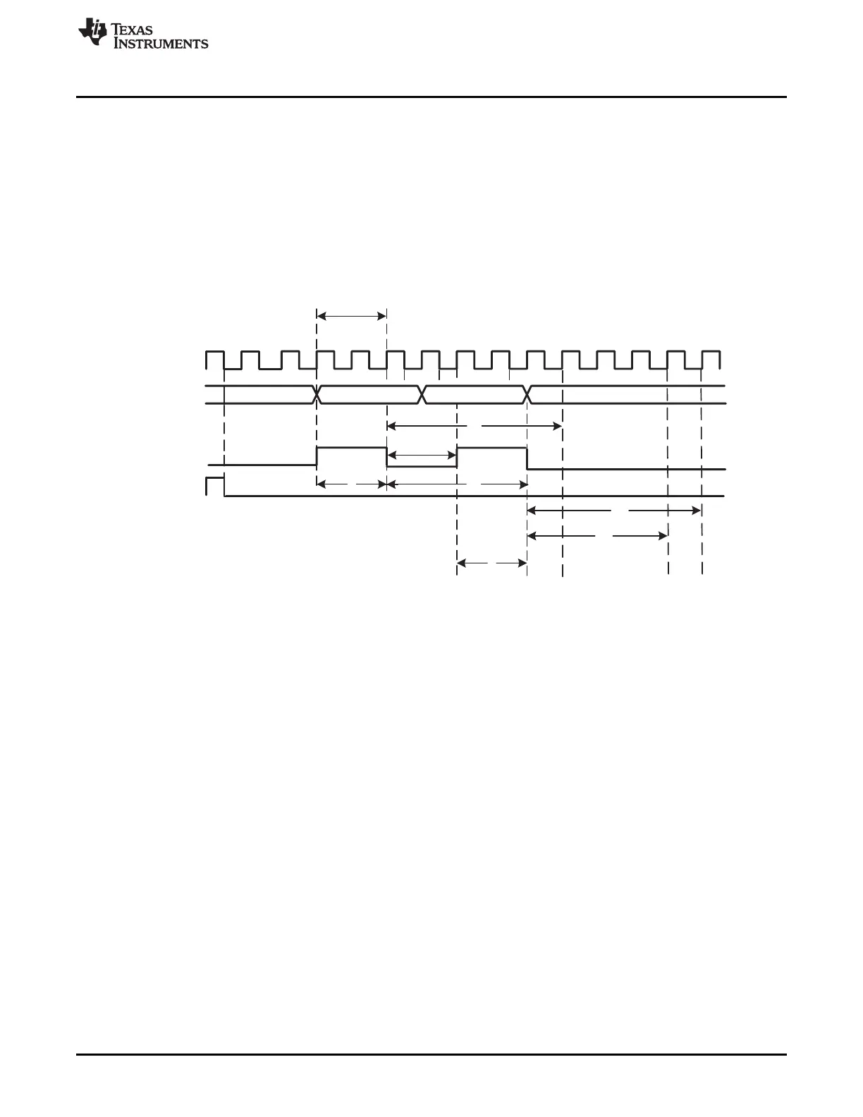
7.3.2.2 Simultaneous Sampling Mode
The ADC has the ability to sample two ADCINxx inputs simultaneously, provided that one input is from the
range ADCINA0 - ADCINA7 and the other input is from the range ADCINB0 - ADCINB7. Furthermore, the
two inputs must have the same sample-and-hold offset (i.e., ADCINA4 and ADCINB4, but not ADCINA7
and ADCINB6). To put the ADC into simultaneous sampling mode, the SMODE_SEL bit in the ADCTRL3
register must be set.
Figure 7-11 describes the timing of simultaneous sampling mode. In this example, the ACQ_PS bits are
set to 0001b.
Figure 7-11. Simultaneous Sampling Mode (SMODE = 1)
A ADC channel address contained in [CONV##] 4-bit register; [CONV00].
B S
OFF
in simultaneous sampling mode is 2 ADC clocks to allow for S/H circuit availability until the B channel sampled
voltage is passed to the converter.
Legend:
C1 Time from end of acquisition window until Ax channel result in result register
C2 Time from end of acquisition window until Bx channel result in result register
S Acquisition window
S
OFF
Acquisition HOLD OFF
 Loading...