SYNCI
CTR=PRD
Disable
Disable
Sync out
select
ECCTL2[SYNCOSEL]
SYNCO
ECCTL2[SWSYNC]
SYNC
ECCTL2[SYNCI_EN]
CTRPHS
LD_CTRPHS
CLK
TSCTR
(counter 32b)
RST
OVF
SYSCLK
Delta−mode
CTR−OVF
CTR[31−0]
www.ti.com
Capture Mode Description
359
SPRUI07–March 2020
Submit Documentation Feedback
Copyright © 2020, Texas Instruments Incorporated
Enhanced Capture (eCAP)
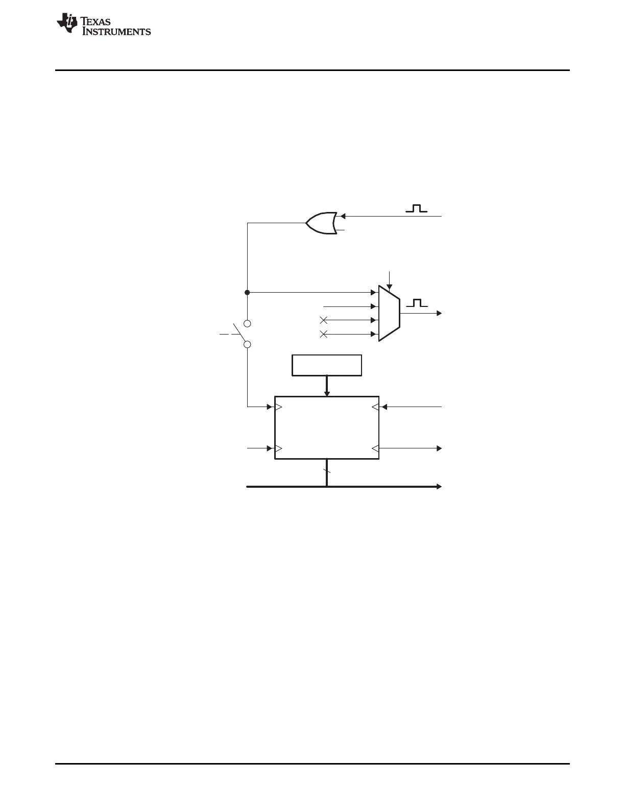
5.5.4 32-Bit Counter and Phase Control
This counter provides the time-base for event captures, and is clocked via the system clock.
A phase register is provided to achieve synchronization with other counters, via a hardware and software
forced sync. This is useful in APWM mode when a phase offset between modules is needed.
On any of the four event loads, an option to reset the 32-bit counter is given. This is useful for time
difference capture. The 32-bit counter value is captured first, then it is reset to 0 by any of the LD1-LD4
signals.
Figure 5-8. Details of the Counter and Synchronization Block
5.5.5 CAP1-CAP4 Registers
These 32-bit registers are fed by the 32-bit counter timer bus, CTR[0-31] and are loaded (capture a time-
stamp) when their respective LD inputs are strobed.
Control bit CAPLDEN can inhibit loading of the capture registers. During one-shot operation, this bit is
cleared (loading is inhibited) automatically when a stop condition occurs, StopValue = Mod4.
CAP1 and CAP2 registers become the active period and compare registers, respectively, in APWM mode.
CAP3 and CAP4 registers become the respective shadow registers (APRD and ACMP) for CAP1 and
CAP2 during APWM operation.
5.5.6 Interrupt Control
Operation and features of eCAP Interrupt Control include:
• An Interrupt can be generated on capture events (CEVT1-CEVT4, CTROVF) or APWM events (CTR =
PRD, CTR = CMP).
• A counter overflow event (FFFFFFFF->00000000) is also provided as an interrupt source (CTROVF).
• The capture events are edge and sequencer-qualified (ordered in time) by the polarity select and Mod4
gating, respectively.
 Loading...