28x
Master
SDAA
SCLA
SDA SCL
SDA
SCL
I2C
EEPROM
SlaveAddress
0x50
www.ti.com
Bootloader Features
207
SPRUI07–March 2020
Submit Documentation Feedback
Copyright © 2020, Texas Instruments Incorporated
Boot ROM
2.2.21 I2C Boot Function
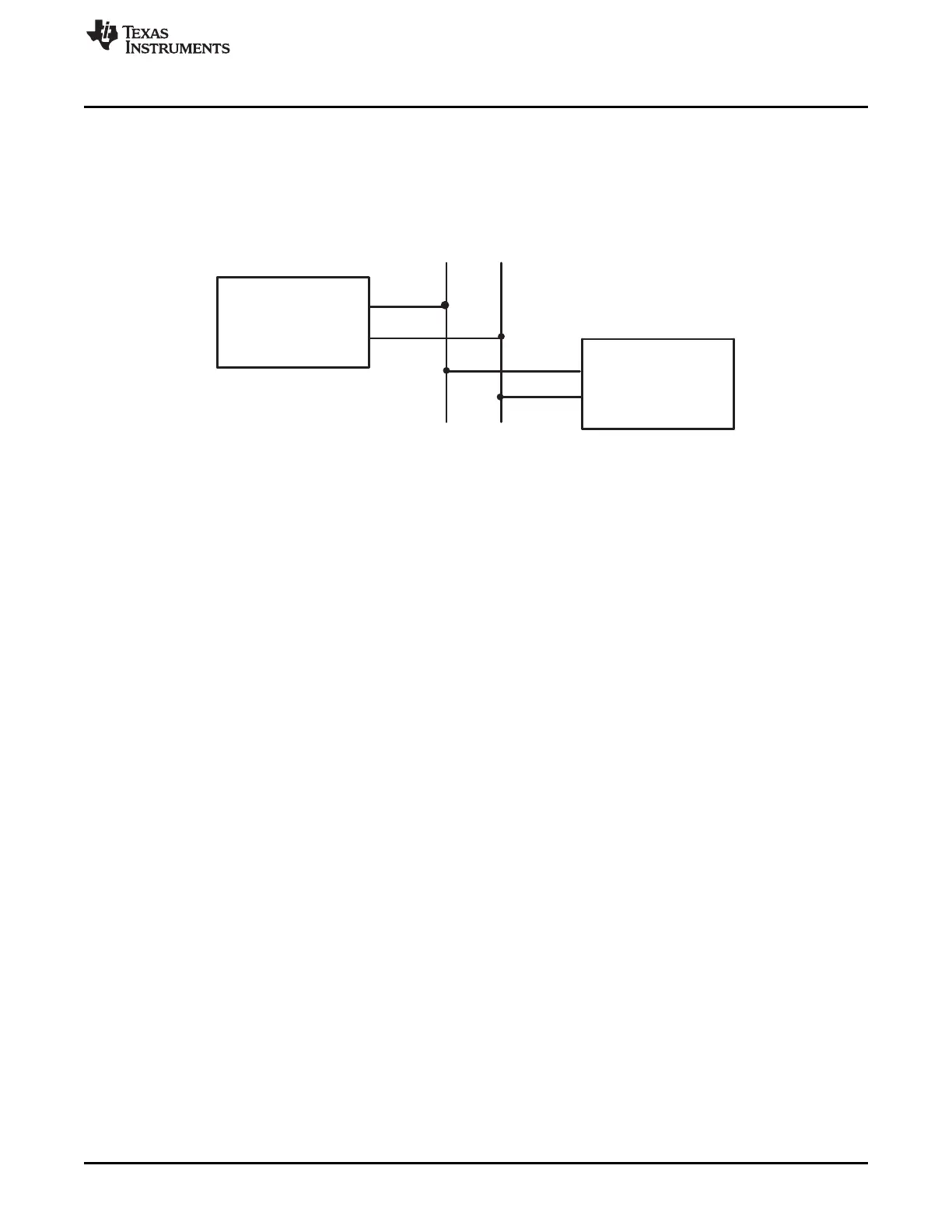
The I2C bootloader expects an 8-bit wide I2C-compatible EEPROM device to be present at address 0x50
on the I2C-A bus as indicated in Figure 2-33. The EEPROM must adhere to conventional I2C EEPROM
protocol, as described in this section, with a 16-bit base address architecture.
Figure 2-33. EEPROM Device at Address 0x50
The I2C loader uses following pins:
• SDAA on GPIO32
• SCLA on GPIO33
If the download is to be performed from a device other than an EEPROM, then that device must be set up
to operate in the slave mode and mimic the I2C EEPROM. Immediately after entering the I2C boot
function, the GPIO pins are configured for I2C-A operation and the I2C is initialized. The following
requirements must be met when booting from the I2C module:
• The input frequency to the device must be in the appropriate range.
• The EEPROM must be at slave address 0x50.
To use the I2C-A bootloader, the input clock frequency to the device must be between 28 MHz and
48 MHz. This input clock frequency will result in a default 14 MHz to 24 MHz system clock (SYSCLKOUT).
By default, the bootloader sets the I2CPSC prescale value to 1 so that the I2C clock will be divided down
from SYSCLKOUT. This results in an I2C clock between 7 MHz and 12 MHz, which meets the I2C
peripheral clocking specification. The I2CPSC value can be modified after receiving the first few bytes
from the EEPROM, but it is not advisable to do this, because this can cause the I2C to operate out of the
required specification.
The bit-period prescalers (I2CCLKH and I2CCLKL) are configured by the bootloader to run the I2C at a
50 percent duty cycle at 100-kHz bit rate (standard I2C mode) when the system clock is 12 MHz. These
registers can be modified after receiving the first few bytes from the EEPROM. This allows the
communication to be increased up to a 400-kHz bit rate (fast I2C mode) during the remaining data reads.
Arbitration, bus busy, and slave signals are not checked. Therefore, no other master is allowed to control
the bus during this initialization phase. If the application requires another master during I2C boot mode,
that master must be configured to hold off sending any I2C messages until the application software
signals that it is past the bootloader portion of initialization.
 Loading...