CEVT1
CEVT2
CEVT5
FFFFFFFF
CTR[0−31]
00000000
CAPxpin
t
MOD4
CTR
CAP1
CAP2
CAP3
CAP4
Captureregisters[1−4]
CEVT3
CEVT4
0 1 2 3 0 1
XX
XX
t
2
XX
t
3
XX
t
4
CTRvalueatCEVT1
t
1
T
1
T
2
2 3 0
t
5
t
6
t
7
T
3
T
4
T
5
T
6
T
7
T
8
CEVT1
CEVT2
CEVT3
CEVT4
Polarityselection
www.ti.com
Application of the eCAP Module
367
SPRUI07–March 2020
Submit Documentation Feedback
Copyright © 2020, Texas Instruments Incorporated
Enhanced Capture (eCAP)
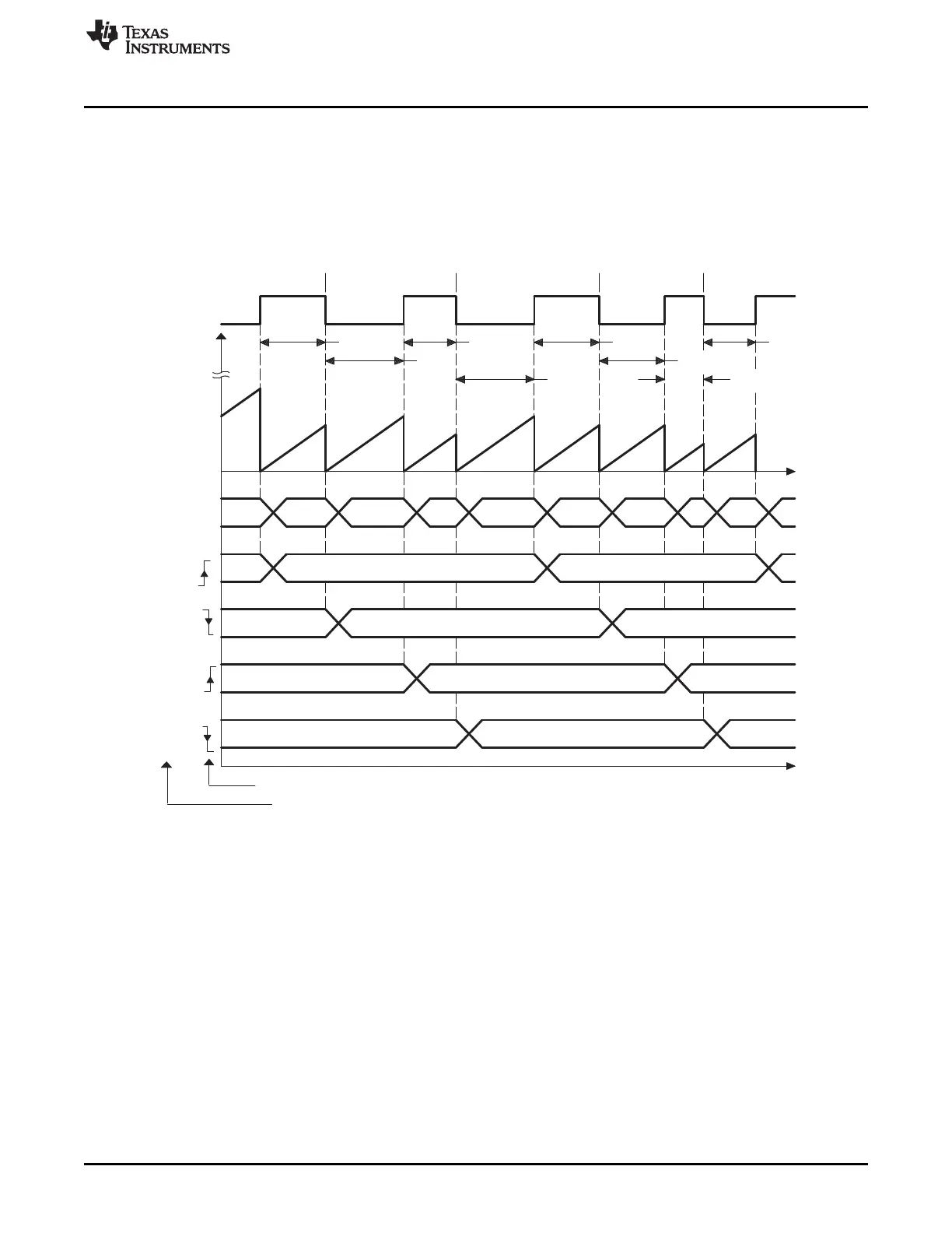
5.6.4 Example 4 - Time Difference (Delta) Operation Rising and Falling Edge Trigger
In Figure 5-15 the eCAP operating mode is almost the same as in previous section except Capture events
are qualified as either Rising or Falling edge, this now gives both Period and Duty cycle information, that
is: Period1 = T
1
+T
2
, Period2 = T
3
+T
4
, …and so on, Duty Cycle1 (on-time %) = T
1
/ Period1 x 100%, Duty
Cycle1 (off-time %) = T
2
/ Period1 x 100%, and so on.
Figure 5-15. Capture Sequence for Delta Mode Time-stamp With Rising and Falling Edge Detect
During initialization, you must write to the active registers for both period and compare. This action will
automatically copy the init values into the shadow values. For subsequent compare updates during run-
time, the shadow registers must be used.
 Loading...