www.ti.com
XINTF Registers
857
SPRUI07–March 2020
Submit Documentation Feedback
Copyright © 2020, Texas Instruments Incorporated
External Interface (XINTF)
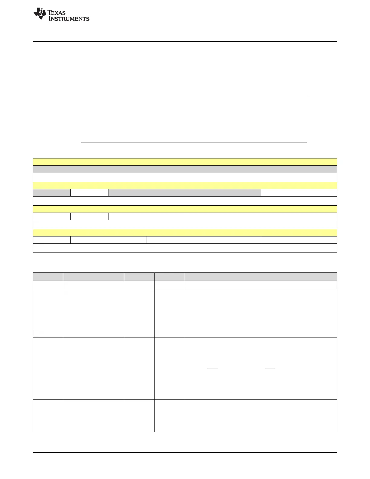
14.6.4 XTIMING7 Register (Offset = B2Eh) [reset = 41D2A5h]
XTIMING7 is shown in Figure 14-9 and described in Table 14-11.
Each XINTF zone has one timing register. Changes to this register will affect the timing of that particular
zone. Changes to a zone’s timing register should be made only by code executing outside of that zone.
This register is EALLOW protected.
NOTE:
• Minimum wait-state requirements for different modes are shown in Section 14.2.
• The external device to which the 28x is interfaced may have additional timing
constraints. See the vendor documentation for details.
• No logic is included to detect illegal settings.
Figure 14-9. XTIMING7 Register
31 30 29 28 27 26 25 24
RESERVED
R-0h
23 22 21 20 19 18 17 16
RESERVED X2TIMING RESERVED XSIZE
R-0h R/W-1h R-0h R/W-1h
15 14 13 12 11 10 9 8
READYMODE USEREADY XRDLEAD XRDACTIVE XRDTRAIL
R/W-1h R/W-1h R/W-1h R/W-1h R/W-1h
7 6 5 4 3 2 1 0
XRDTRAIL XWRLEAD XWRACTIVE XWRTRAIL
R/W-1h R/W-1h R/W-1h R/W-1h
Table 14-11. XTIMING7 Register Field Descriptions
Bit Field Type Reset Description
31-23 RESERVED R 0h
Reserved
22 X2TIMING R/W 1h
This bit specifies the scaling factor of the XRDLEAD, XRDACTIVE,
XRDTRAIL, XWRLEAD, XWRACTIVE, and XWRTRAIL values for
the zone.
0h = The values are scaled 1:1
1h = The values are scaled 2:1 (doubled). This the default mode of
operation on power up and reset.
21-18 RESERVED R 0h
17-16 XSIZE R/W 1h These two bits must always be written to as either 0, 1 (32-bit data
bus) or 1, 1 (16-bit data bus). Any other combination is reserved and
will result in incorrect XINTF behavior.
0h = Reserved - results in incorrect XINTF behavior
1h = 32-bit interface. In this mode the zone will use all 32 data lines.
The XA0/WE1 signal will behave as WE1 as described in
Section 14.2.7.
2h = Reserved - results in incorrect XINTF behavior
3h = 16-bit interface. In this mode the zone will only use 16 data
lines. The XA0/WE1 signal will behave as XA0. (default at reset)
15 READYMODE R/W 1h Sets the XREADY input sampling for the zone as synchronous or
asynchronous. This bit is ignored if XREADY is not sampled
(USEREADY = 0).
0h = XREADY input is synchronous for the zone.
1h = XREADY input is asynchronous for the zone. (default at reset)
 Loading...