0
1
EXTSOCAG1
POLSEL
PulseStretcher
,
32HSPCLKCyclesW
ideandThentoChipPins
EXTSOCAG1
ePWM2
ePWM2SOCA
ePWM2SOCB
ePWM1
ePWM1SOCA
ePWM1SOCB
ePWM3
ePWM3SOCA
ePWM3SOCB
ePWM4
ePWM4SOCA
ePWM4SOCB
0
1
EXTSOCAG4
POLSEL
EXTSOCAG4
ePWM6
ePWM6SOCA
ePWM6SOCB
ePWM5
ePWM5SOCA
ePWM5SOCB
ePWM7
ePWM7SOCA
ePWM7SOCB
ePWM8
ePWM8SOCA
ePWM4SOCB
0
1
EXTSOCBG1
POLSEL
EXTSOCSBG1
0
1
EXTSOCBG4
POLSEL
EXTSOCBG4
ePWM9
ePWM9SOCA
ePWM9SOCB
0
1
EXTSOCAG7
POLSEL
EXTSOCAG7
0
1
EXTSOCBG7
POLSEL
EXTSOCBG7
ePWM Submodules
www.ti.com
270
SPRUI07–March 2020
Submit Documentation Feedback
Copyright © 2020, Texas Instruments Incorporated
Enhanced Pulse Width Modulator (ePWM) Module
3.2.8.1 Operational Overview of the Event-Trigger Submodule
The following sections describe the event-trigger submodule's operational highlights.
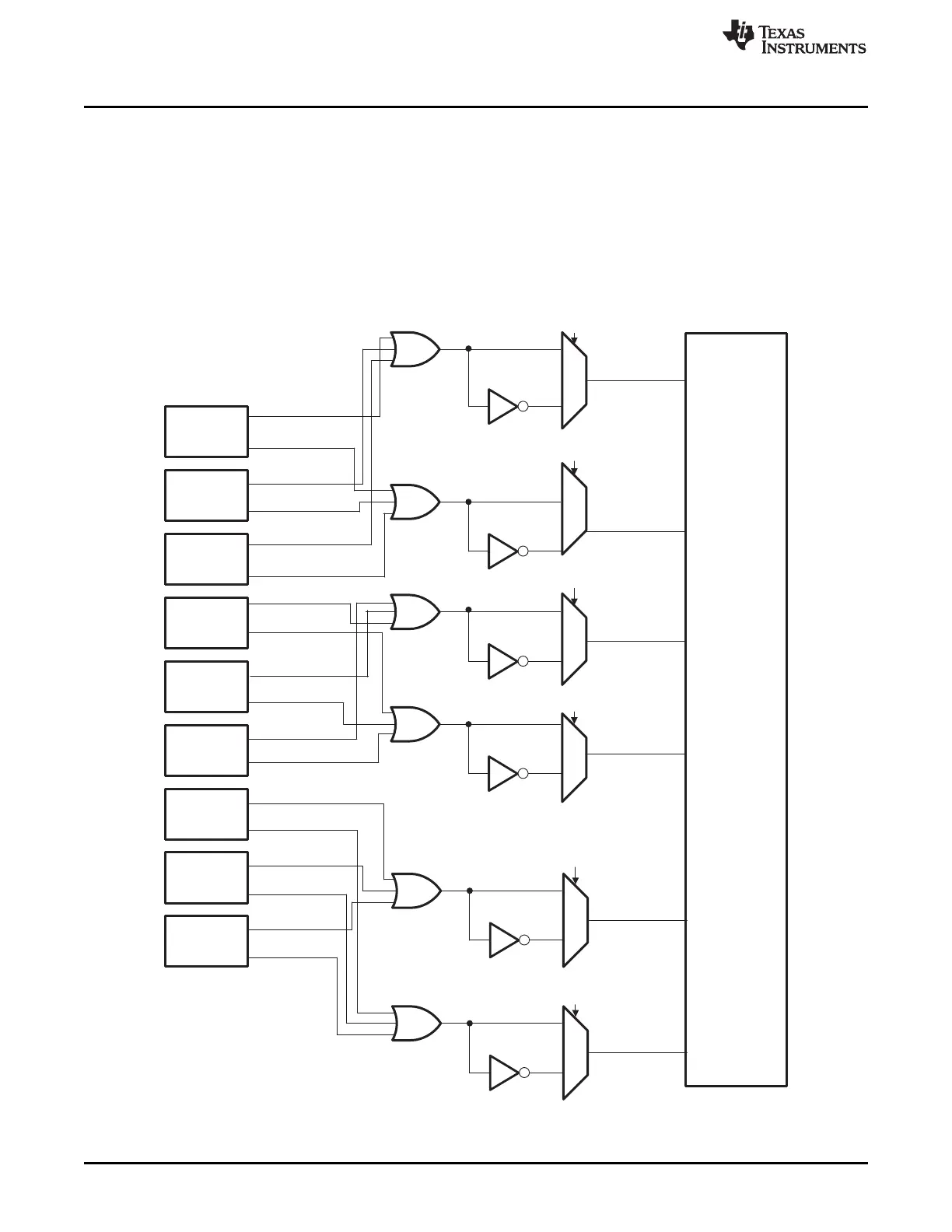
Each ePWM module has one interrupt request line connected to the PIE and two start of conversion
signals (one for each sequencer) connected to the ADC module. As shown in Figure 3-40, ADC start of
conversion for all ePWM modules are ORed together and hence multiple modules can initiate an ADC
start of conversion. If two requests occur on one start of conversion line, then only one will be recognized
by the ADC.
Figure 3-40. Event-Trigger Submodule Inter-Connectivity of ADC Start of Conversion
 Loading...