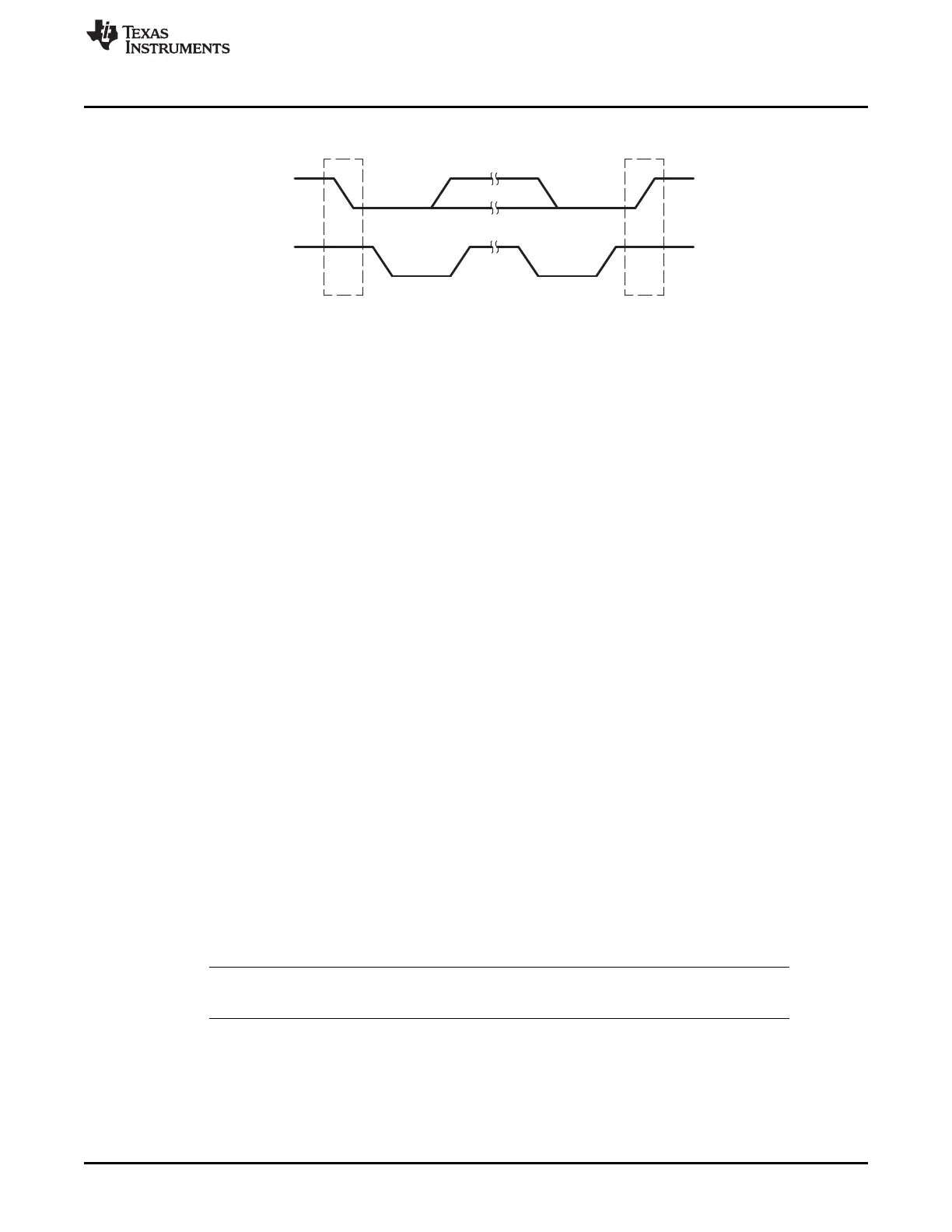
SDA
SCL
START
condition (S)
condition (P)
STOP
www.ti.com
I2C Module Operational Details
623
SPRUI07–March 2020
Submit Documentation Feedback
Copyright © 2020, Texas Instruments Incorporated
Inter-Integrated Circuit Module (I2C)
Figure 11-6. I2C Module START and STOP Conditions
After a START condition and before a subsequent STOP condition, the I2C bus is considered busy, and
the bus busy (BB) bit of I2CSTR is 1. Between a STOP condition and the next START condition, the bus
is considered free, and BB is 0.
For the I2C module to start a data transfer with a START condition, the master mode bit (MST) and the
START condition bit (STT) in I2CMDR must both be 1. For the I2C module to end a data transfer with a
STOP condition, the STOP condition bit (STP) must be set to 1. When the BB bit is set to 1 and the STT
bit is set to 1, a repeated START condition is generated. For a description of I2CMDR and its bits
(including MST, STT, and STP), see Registers Section 11.6.
The I2C peripheral cannot detect a START or STOP condition while it is in reset (IRS = 0). The BB bit will
remain in the cleared state (BB = 0) while the I2C peripheral is in reset (IRS = 0). When the I2C peripheral
is taken out of reset (IRS set to 1) the BB bit will not correctly reflect the I2C bus status until a START or
STOP condition is detected.
Follow these steps before initiating the first data transfer with I2C:
1. After taking the I2C peripheral out of reset by setting the IRS bit to 1, wait a period larger than the total
time taken for the longest data transfer in the application. By waiting for a period of time after I2C
comes out of reset, users can ensure that at least one START or STOP condition will have occurred
on the I2C bus and been captured by the BB bit. After this period, the BB bit will correctly reflect the
state of the I2C bus.
2. Check the BB bit and verify that BB = 0 (bus not busy) before proceeding.
3. Begin data transfers.
Not resetting the I2C peripheral in between transfers ensures that the BB bit reflects the actual bus status.
If users must reset the I2C peripheral in between transfers, repeat steps 1 through 3 every time the I2C
peripheral is taken out of reset.
11.3.5 Serial Data Formats
Figure 11-7 shows an example of a data transfer on the I2C bus. The I2C module supports 1 to 8-bit data
values. In Figure 11-7, 8-bit data is transferred. Each bit put on the SDA line equates to 1 pulse on the
SCL line, and the values are always transferred with the most significant bit (MSB) first. The number of
data values that can be transmitted or received is unrestricted. The serial data format used in Figure 11-7
is the 7-bit addressing format. The I2C module supports the formats shown in Figure 11-8 through
Figure 11-10 and described in the paragraphs that follow the figures.
NOTE: In Figure 11-7 through Figure 11-10, n = the number of data bits (from 1 to 8) specified by
the bit count (BC) field of I2CMDR.
 Loading...