(R/X)SYNCERR
D(R/X)
FS(R/X)
CLK(R/X)
C4C5C6C7B0B1B2B3B4B5B6B7A0
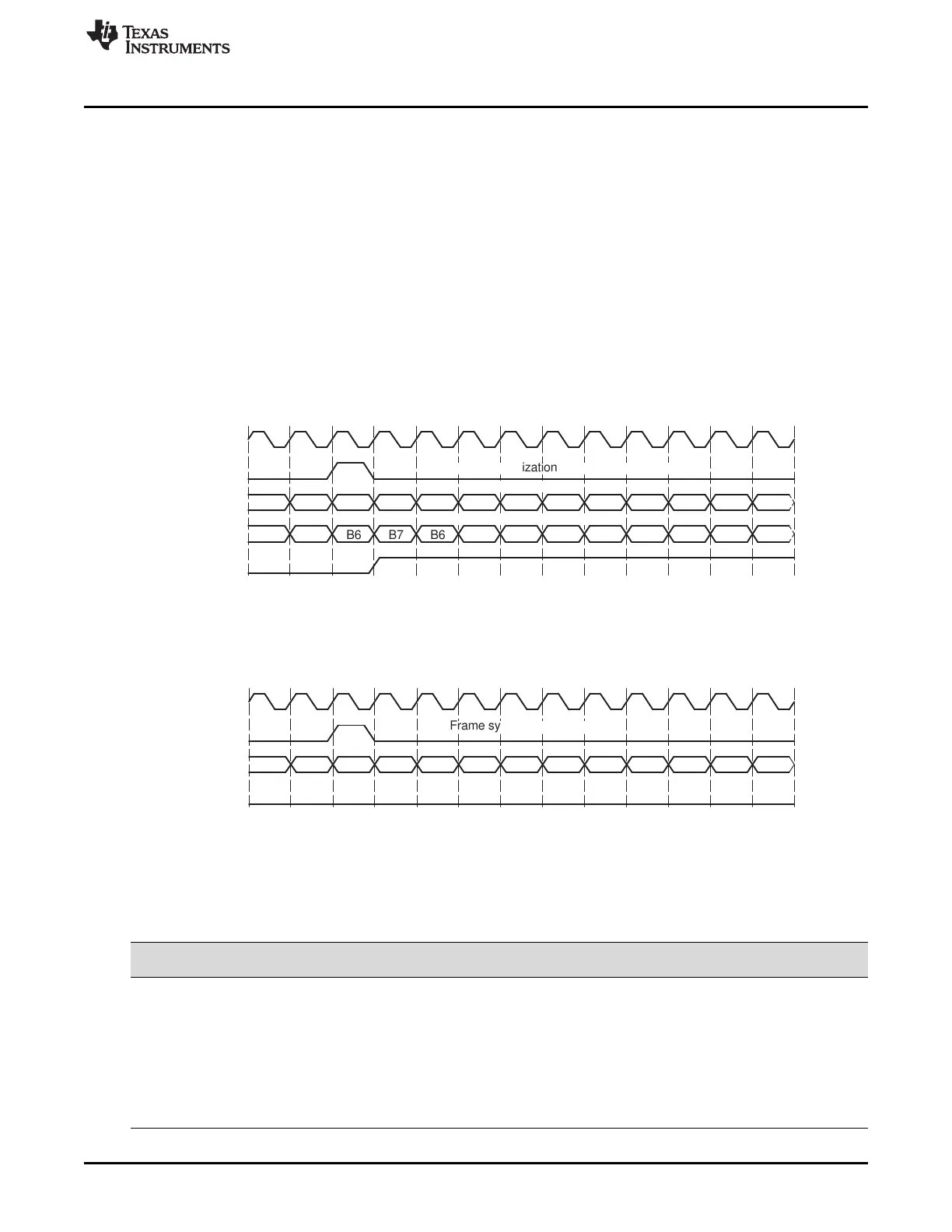
Frame synchronization ignored
Current data retransmitted
New data received
(R/X)SYNCERR
DX
DR
FS(R/X)
CLK(R/X)
C6C7B0
B2B3B4B5B7 B6B6B7A0 B1
D6D7C0C1C2C3C4C5C6C7B6B7A0
Frame synchronization aborts current transfer
www.ti.com
Receiver Configuration
705
SPRUI07–March 2020
Submit Documentation Feedback
Copyright © 2020, Texas Instruments Incorporated
Multichannel Buffered Serial Port (McBSP)
When RFIG = 0, an unexpected FSR pulse causes the McBSP to discard the contents of RSR[1,2] in
favor of the new incoming data. Therefore, if RFIG = 0 and an unexpected frame-synchronization pulse
occurs, the serial port:
1. Aborts the current data transfer
2. Sets RSYNCERR in SPCR1 to 1
3. Begins the transfer of a new data word
For more details about the frame-synchronization error condition, see Section 12.5.3.
12.8.10.2 Examples of Effects of RFIG
Figure 12-43 shows an example in which word B is interrupted by an unexpected frame-synchronization
pulse when (R/X)FIG = 0. In the case of reception, the reception of B is aborted (B is lost), and a new data
word C in this example) is received after the appropriate data delay. This condition is a receive
synchronization error, which sets the RSYNCERR bit.
Figure 12-43. Unexpected Frame-Synchronization Pulse With (R/X)FIG = 0
In contrast with Figure 12-43, Figure 12-44 shows McBSP operation when unexpected frame-
synchronization signals are ignored (when (R/X)FIG = 1). Here, the transfer of word B is not affected by
an unexpected pulse.
Figure 12-44. Unexpected Frame-Synchronization Pulse With (R/X)FIG = 1
12.8.11 Receive Companding Mode
The RCOMPAND bits (see Table 12-30) determine whether companding or another data transfer option is
chosen for McBSP reception.
Table 12-30. Register Bits Used to Set the Receive Companding Mode
Regist
er Bit Name Function Type
Reset
Value
RCR2 4-3 RCOMPAND Receive companding mode R/W 00
Modes other than 00b are enabled only when the appropriate RWDLEN is
000b, indicating 8-bit data.
RCOMPAND = 00 No companding, any size data, MSB received first
RCOMPAND = 01 No companding, 8-bit data, LSB received first (for details,
see Section 12.8.11.4).
RCOMPAND = 10 μ-law companding, 8-bit data, MSB received first
RCOMPAND = 11 A-law companding, 8-bit data, MSB received first
 Loading...