www.ti.com
Peripheral Interrupt Expansion (PIE)
155
SPRUI07–March 2020
Submit Documentation Feedback
Copyright © 2020, Texas Instruments Incorporated
System Control and Interrupts
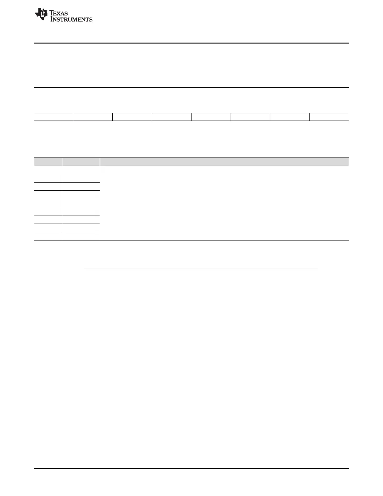
1.6.4.3 PIE Interrupt Enable Registers
There are twelve PIEIER registers, one for each CPU interrupt used by the PIE module (INT1-INT12).
Figure 1-86. PIE Interrupt Enable Register (PIEIERx, x = 1 to 12)
15 8
Reserved
R-0
7 6 5 4 3 2 1 0
INTx.8 INTx.7 INTx.6 INTx.5 INTx.4 INTx.3 INTx.2 INTx.1
R/W-0 R/W-0 R/W-0 R/W-0 R/W-0 R/W-0 R/W-0 R/W-0
LEGEND: R/W = Read/Write; R = Read only; -n = value after reset
Table 1-116. PIE Interrupt Enable Register (PIEIERx) Field Descriptions
Bits Field Description
15-8 Reserved Reserved
7 INTx.8 These register bits individually enable an interrupt within a group and behave very much like the core interrupt
enable register. Setting a bit to 1 enables the servicing of the respective interrupt. Setting a bit to 0 disables
the servicing of the interrupt. x = 1 to 12. INTx means CPU INT1 to INT12
6 INTx.7
5 INTx.6
4 INTx.5
3 INTx.4
2 INTx.3
1 INTx.2
0 INTx.1
NOTE: Care must be taken when clearing PIEIER bits during normal operation. See Section
Section 1.6.3.2 for the proper procedure for handling these bits.
 Loading...