T =1000ns
PWM
EPWM1A
0 100
60ns
30ns
(F =1MHz)
PWM
3 6
SYSCLKOUT =
TBCLK=
100MHz
Operational Description of HRPWM
www.ti.com
334
SPRUI07–March 2020
Submit Documentation Feedback
Copyright © 2020, Texas Instruments Incorporated
High-Resolution Pulse Width Modulator (HRPWM)
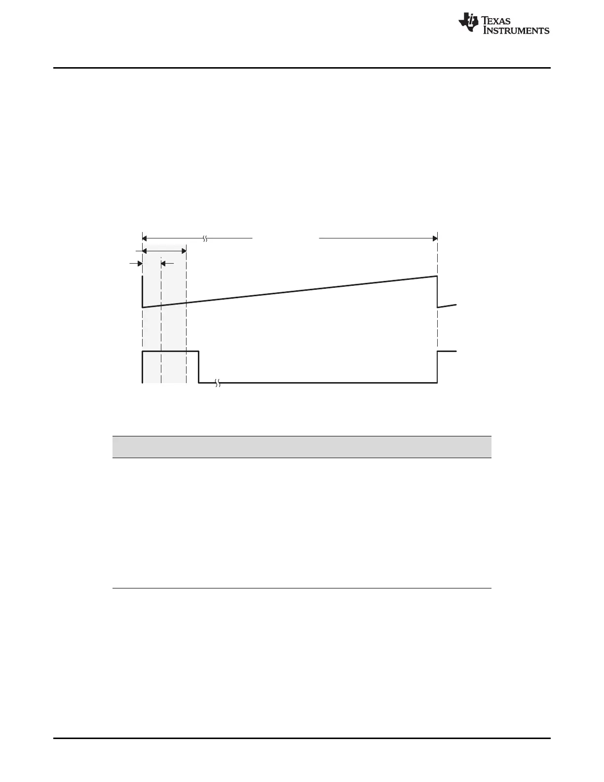
4.2.3.3 Duty Cycle Range Limitation
In high resolution mode, the MEP is not active for 100% of the PWM period. It becomes operational:
• 3 SYSCLK cycles after the period starts when diagnostics are disabled
• 6 SYSCLK cycles after the period starts when SFO diagnostics are running
Duty cycle range limitations are illustrated in Figure 4-6 . This limitation imposes a lower duty cycle limit on
the MEP. For example, precision edge control is not available all the way down to 0% duty cycle. Although
for the first 3 or 6 cycles, the HRPWM capabilities are not available, regular PWM duty control is still fully
operational down to 0% duty. In most applications this should not be an issue as the controller regulation
point is usually not designed to be close to 0% duty cycle. To better understand the useable duty cycle
range, see Table 4-5.
Figure 4-6. Low % Duty Cycle Range Limitation Example When PWM Frequency = 1 MHz
(1)
System clock - T
SYSCLKOUT
= 10 ns
System clock = TBCLK = 100 MHz
Table 4-5. Duty Cycle Range Limitation for 3 and 6 SYSCLK/TBCLK Cycles
PWM Frequency
(1)
(kHz)
3 Cycles
Minimum Duty
6 Cycles SYSCLKOUT
Minimum Duty
200 0.6% 1.2%
400 1.2% 2.4%
600 1.8% 3.6%
800 2.4% 4.8%
1000 3.0% 6.0%
1200 3.6% 7.2%
1400 4.2% 8.4%
1600 4.8% 9.6%
1800 5.4% 10.8%
2000 6.0% 12.0%
If the application demands HRPWM operation in the low percent duty cycle region, then the HRPWM can
be configured to operate in count-down mode with the rising edge position (REP) controlled by the MEP.
This is illustrated in Figure 4-7. In this case, low percent duty limitation is no longer an issue. However,
there will be a maximum duty limitation with same percent numbers as given in Table 4-5 .
 Loading...