1
7 n 7 n
1 1 1 1 1 1 1 1
S Slave address
R/W
ACK
Data
ACK
S Slave address
R/W ACK
Data
ACK
P
1
Any
number
1
Any number
DataDataS
1
DataACK ACK ACK P
1
n n n
111
www.ti.com
I2C Module Operational Details
625
SPRUI07–March 2020
Submit Documentation Feedback
Copyright © 2020, Texas Instruments Incorporated
Inter-Integrated Circuit Module (I2C)
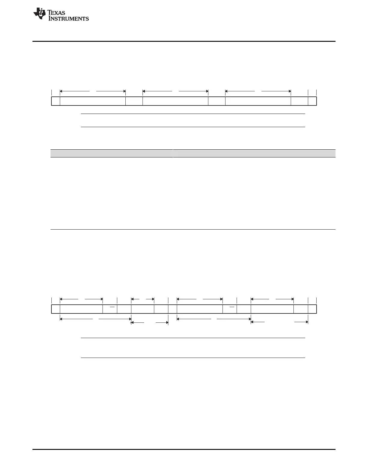
In this format (see Figure 11-10), the first byte after a START condition (S) is a data byte. An ACK bit is
inserted after each data byte, which can be from 1 to 8 bits, depending on the BC field of I2CMDR. No
address or data-direction bit is sent. Therefore, the transmitter and the receiver must both support the free
data format, and the direction of the data must be constant throughout the transfer.
Figure 11-10. I2C Module Free Data Format (FDF = 1 in I2CMDR)
NOTE: The free data format is not supported in the digital loopback mode (I2CMDR.DLB = 1).
Table 11-4. How the MST and FDF Bits of I2CMDR Affect the Role of the TRX Bit of I2CMDR
MST FDF I2C Module State Function of TRX
0 0 In slave mode but not free data
format mode
TRX is a don’t care. Depending on the command from the master, the I2C
module responds as a receiver or a transmitter.
0 1 In slave mode and free data
format mode
The free data format mode requires that the I2C module remains the
transmitter or the receiver throughout the transfer. TRX identifies the role
of the I2C module:
TRX = 1: The I2C module is a transmitter.
TRX = 0: The I2C module is a receiver.
1 0 In master mode but not free data
format mode
TRX = 1: The I2C module is a transmitter.
TRX = 0: The I2C module is a receiver.
1 1 In master mode and free data
format mode
TRX = 0: The I2C module is a receiver.
TRX = 1: The I2C module is a transmitter.
11.3.5.4 Using a Repeated START Condition
I2C master can communicate with multiple slave addresses without having to give up control of the I2C
bus by driving a STOP condition. This can be achieved by driving another START condition at the end of
each data type. The repeated START condition can be used with the 7-bit addressing, 10-bit addressing,
and free data formats. Figure 11-11 shows a repeated START condition in the 7-bit addressing format.
Figure 11-11. Repeated START Condition (in This Case, 7-Bit Addressing Format)
NOTE: In Figure 11-11, n = the number of data bits (from 1 to 8) specified by the bit count (BC) field
of I2CMDR.
11.3.6 NACK Bit Generation
When the I2C module is a receiver (master or slave), it can acknowledge or ignore bits sent by the
transmitter. To ignore any new bits, the I2C module must send a no-acknowledge (NACK) bit during the
acknowledge cycle on the bus. Table 11-5 summarizes the various ways you can tell the I2C module to
send a NACK bit.
 Loading...