www.ti.com
Registers
311
SPRUI07–March 2020
Submit Documentation Feedback
Copyright © 2020, Texas Instruments Incorporated
Enhanced Pulse Width Modulator (ePWM) Module
3.4.5 PWM-Chopper Submodule Control Register
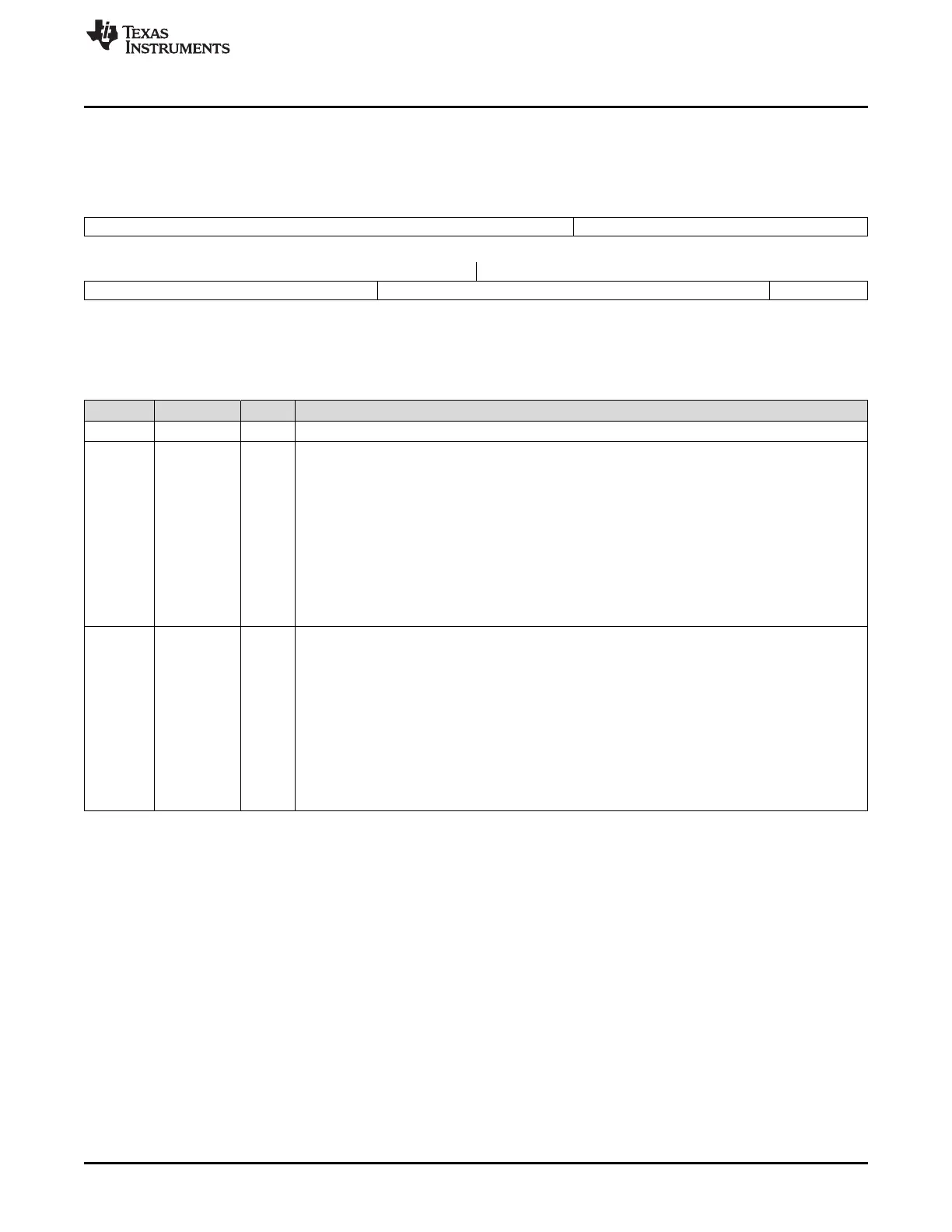
Figure 3-77 and Table 3-37 provide the definitions for the PWM-chopper submodule control register.
Figure 3-77. PWM-Chopper Control Register (PCCTL)
15 11 10 8
Reserved CHPDUTY
R-0 R/W-0
7 5 4 1 0
CHPFREQ OSHTWTH CHPEN
R/W-0 R/W-0 R/W-0
LEGEND: R/W = Read/Write; R = Read only; -n = value after reset
Table 3-37. PWM-Chopper Control Register (PCCTL) Bit Descriptions
Bits Name Value Description
15-11 Reserved Reserved
10-8 CHPDUTY Chopping Clock Duty Cycle
000 Duty = 1/8 (12.5%)
001 Duty = 2/8 (25.0%)
010 Duty = 3/8 (37.5%)
011 Duty = 4/8 (50.0%)
100 Duty = 5/8 (62.5%)
101 Duty = 6/8 (75.0%)
110 Duty = 7/8 (87.5%)
111 Reserved
7:5 CHPFREQ Chopping Clock Frequency
000 Divide by 1 (no prescale, = 12.5 MHz at 100 MHz SYSCLKOUT)
001 Divide by 2 (6.25 MHz at 100 MHz SYSCLKOUT)
010 Divide by 3 (4.16 MHz at 100 MHz SYSCLKOUT)
011 Divide by 4 (3.12 MHz at 100 MHz SYSCLKOUT)
100 Divide by 5 (2.50 MHz at 100 MHz SYSCLKOUT)
101 Divide by 6 (2.08 MHz at 100 MHz SYSCLKOUT)
110 Divide by 7 (1.78 MHz at 100 MHz SYSCLKOUT)
111 Divide by 8 (1.56 MHz at 100 MHz SYSCLKOUT)
 Loading...