1
SDA LINE
001
START
0 0 0 1 0
READ
ACK
ACK
NO ACK
STOP
Device
Address
DATA BYTE n DATA BYTE n+1
1
SDA LINE
START
MSB
LSB
1 0 1 0 0 0 0 0 0 0 0 0 0 0 0 0
WRITE
ACK
0 0 0 0 0 0 0 00
0
00 0
0
ACK
1
RESTART
MSB
0 0 0
LSB
1 0
READ
ACK
ACK
NO ACK
STOP
Device
Address
Address
Pointer, MSB
Address
Pointer, LSB
ACK
Device
Address
DATA BYTE 1 DATA BYTE 2
www.ti.com
Bootloader Features
209
SPRUI07–March 2020
Submit Documentation Feedback
Copyright © 2020, Texas Instruments Incorporated
Boot ROM
Table 2-14. I2C 8-Bit Data Stream
Byte Contents
1 LSB: AA (KeyValue for memory width = 8 bits)
2 MSB: 08h (KeyValue for memory width = 8 bits)
3 LSB: I2CPSC[7:0]
4 reserved
5 LSB: I2CCLKH[7:0]
6 MSB: I2CCLKH[15:8]
7 LSB: I2CCLKL[7:0]
8 MSB: I2CCLKL[15:8]
...
...
...
Data for this section.
17 LSB: Reserved for future use
18 MSB: Reserved for future use
19 LSB: Upper half of entry point PC
20 MSB: Upper half of entry point PC[22:16] (Note: Always 0x00)
21 LSB: Lower half of entry point PC[15:8]
22 MSB: Lower half of entry point PC[7:0]
...
...
...
Data for this section.
...
Blocks of data in the format size/destination address/data as shown in the generic data stream description.
...
...
...
Data for this section.
LSB: 00h
n+1 MSB: 00h - indicates the end of the source
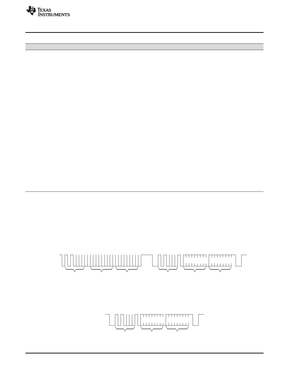
The I2C EEPROM protocol required by the I2C bootloader is shown in Figure 2-35 and Figure 2-36. The
first communication, which sets the EEPROM address pointer to 0x0000 and reads the KeyValue
(0x08AA) from it, is shown in Figure 2-35. All subsequent reads are shown in Figure 2-36 and are read
two bytes at a time.
Figure 2-35. Random Read
Figure 2-36. Sequential Read
 Loading...