www.ti.com
Register Descriptions
521
SPRUI07–March 2020
Submit Documentation Feedback
Copyright © 2020, Texas Instruments Incorporated
Direct Memory Access (DMA) Module
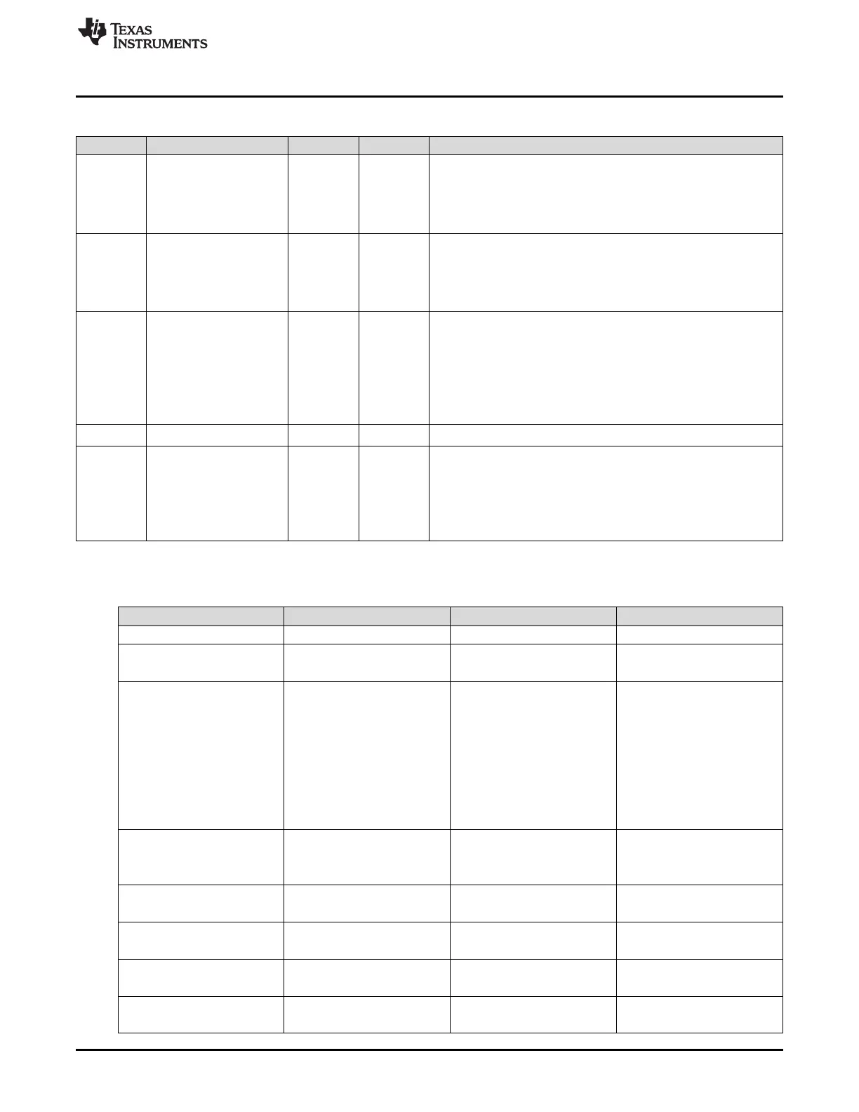
Table 8-8. MODE Register Field Descriptions
(1)(2)(3)
(continued)
Bit Field Type Reset Description
9 CHINTMODE R/W 0h
Channel Interrupt Generation Mode Bit: This bit specifies when the
respective DMA channel interrupt should be generated to the CPU
(via the PIE).
0h = Generate interrupt at beginning of new transfer
1h = Generate interrupt at end of transfer.
8 PERINTE R/W 0h
Peripheral Interrupt Trigger Enable Bit: This bit enables/disables the
selected peripheral interrupt trigger to the DMA.
0h = Interrupt trigger disabled. Neither the selected peripheral nor
software can start a DMA burst.
1h = Interrupt trigger enabled.
7 OVRINTE R/W 0h Overflow Interrupt Enable: This bit when set to 1 enables the DMA to
generate an interrupt when an overflow event is detected.
An overflow interrupt is generated when the PERINTFLG is set and
another interrupt event occurs.
The PERINTFLG being set indicates a previous peripheral event is
latched and has not been serviced by the DMA.
0h = Overflow interrupt disabled
1h = Overflow interrupt enabled
6-5 RESERVED R 0h
Reserved
4-0 PERINTSEL R/W 0h Peripheral Interrupt Source Select Bits: These bits select which
interrupt triggers a DMA burst for the given channel.
Only one interrupt source can be selected.
A DMA burst can also be forced via the PERINTFRC bit.
These bits also select whether the ADCSYNC signal connects to the
channel.
See Table 8-9.
Table 8-9. PREINTSEL Values
Value Interrupt Sync Peripheral
0 None None No Peripheral Connection
1 SEQ1INT ADCSYNC ADC
2 SEQ2INT None
3 XINT1 None External Interrupts
4 XINT2 None
5 XINT3 None
6 XINT4 None
7 XINT5 None
8 XINT6 None
9 XINT7 None
10 XINT13 None
11 TINT0 None CPU Timers
12 TINT1 None
13 TINT2 None
14 MXEVTA None McBSP-A
15 MREVTA None
16 MXEVTB None McBSP-B
17 MREVTB None
18 ePWM1SOCA None ePWM1
19 ePWM1SOCB None
20 ePWM2SOCA None ePWM2
21 ePWM2SOCB None
 Loading...