www.ti.com
Registers
315
SPRUI07–March 2020
Submit Documentation Feedback
Copyright © 2020, Texas Instruments Incorporated
Enhanced Pulse Width Modulator (ePWM) Module
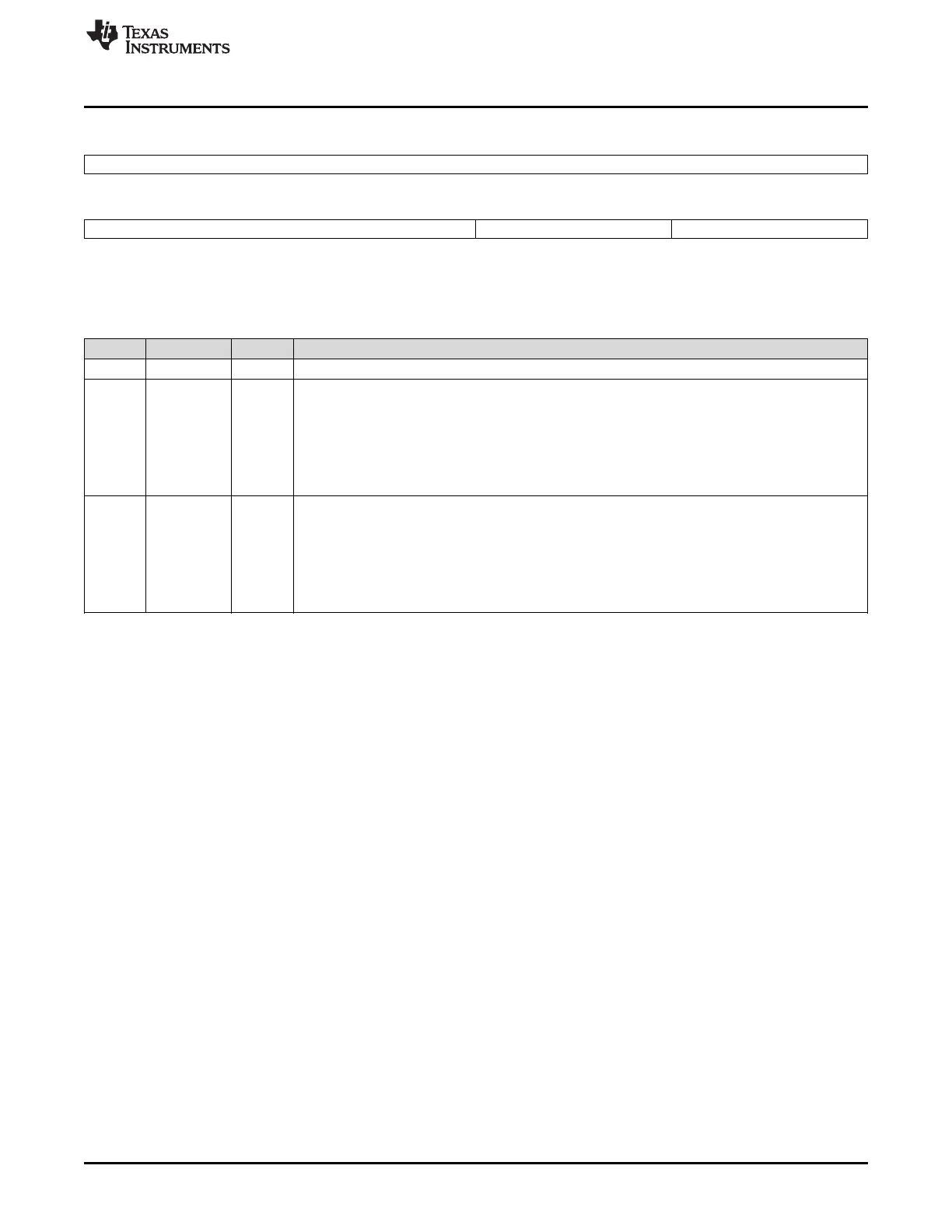
Figure 3-79. Trip-Zone Control Register (TZCTL)
15 8
Reserved
R-0
7 4 3 2 1 0
Reserved TZB TZA
R-0 R/W-0 R/W-0
LEGEND: R/W = Read/Write; R = Read only; -n = value after reset
Table 3-39. Trip-Zone Control Register (TZCTL) Field Descriptions
Bits Name Value Description
15–4 Reserved Reserved
3–2 TZB When a trip event occurs the following action is taken on output EPWMxB. Which trip-zone pins can
cause an event is defined in the TZSEL register.
00 High impedance (EPWMxB = High-impedance state)
01 Force EPWMxB to a high state
10 Force EPWMxB to a low state
11 Do nothing, no action is taken on EPWMxB.
1–0 TZA When a trip event occurs the following action is taken on output EPWMxA. Which trip-zone pins can
cause an event is defined in the TZSEL register.
00 High impedance (EPWMxA = High-impedance state)
01 Force EPWMxA to a high state
10 Force EPWMxA to a low state
11 Do nothing, no action is taken on EPWMxA.
 Loading...