(00)
(10)
(11)
(01)
(A,B)=
QEPA
QEPB
eQEP signals
10
01
00 11
Increment
counter
Decrement
counter
Decrement
counter
Increment
counter
Decrement
counter
Decrement
counter
Increment
counter
Increment
counter
Quadrature Decoder Unit (QDU)
www.ti.com
396
SPRUI07–March 2020
Submit Documentation Feedback
Copyright © 2020, Texas Instruments Incorporated
Enhanced Quadrature Encoder Pulse (eQEP)
6.4.1.1 Quadrature Count Mode
The quadrature decoder generates the direction and clock to the position counter in quadrature count
mode.
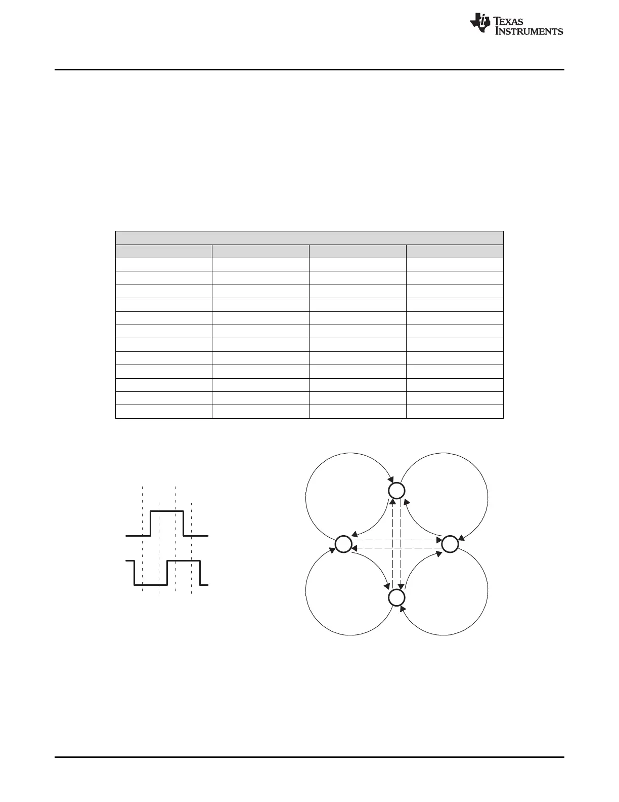
Direction Decoding— The direction decoding logic of the eQEP circuit determines which one of the
sequences (QEPA, QEPB) is the leading sequence and accordingly updates the direction
information in the QEPSTS[QDF] bit. Table 6-2 and Figure 6-6 show the direction decoding logic in
truth table and state machine form. Both edges of the QEPA and QEPB signals are sensed to
generate count pulses for the position counter. Therefore, the frequency of the clock generated by
the eQEP logic is four times that of each input sequence. Figure 6-7 shows the direction decoding
and clock generation from the eQEP input signals.
Table 6-2. Quadrature Decoder Truth Table
.
Previous Edge Present Edge QDIR QPOSCNT
QA↑ QB↑ UP Increment
QB↓ DOWN Decrement
QA↓ TOGGLE Increment or Decrement
QA↓ QB↓ UP Increment
QB↑ DOWN Decrement
QA↑ TOGGLE Increment or Decrement
QB↑ QA↑ DOWN Increment
QA↓ UP Decrement
QB↓ TOGGLE Increment or Decrement
QB↓ QA↓ DOWN Increment
QA↑ UP Decrement
QB↑ TOGGLE Increment or Decrement
Figure 6-6. Quadrature Decoder State Machine
 Loading...