CPU
SYSCLKOUT
Low speed
prescaler
System
control
block
PIE
block
SPIINT/RXINT
TXINT
Registers
SPI
SPIAENCLK LSPCLK
SPISOMI
GPIO
MUX
SPISIMO
SPICLK
SPISTE
Peripheral Bus
SYSRS
Introduction
www.ti.com
550
SPRUI07–March 2020
Submit Documentation Feedback
Copyright © 2020, Texas Instruments Incorporated
Serial Peripheral Interface (SPI)
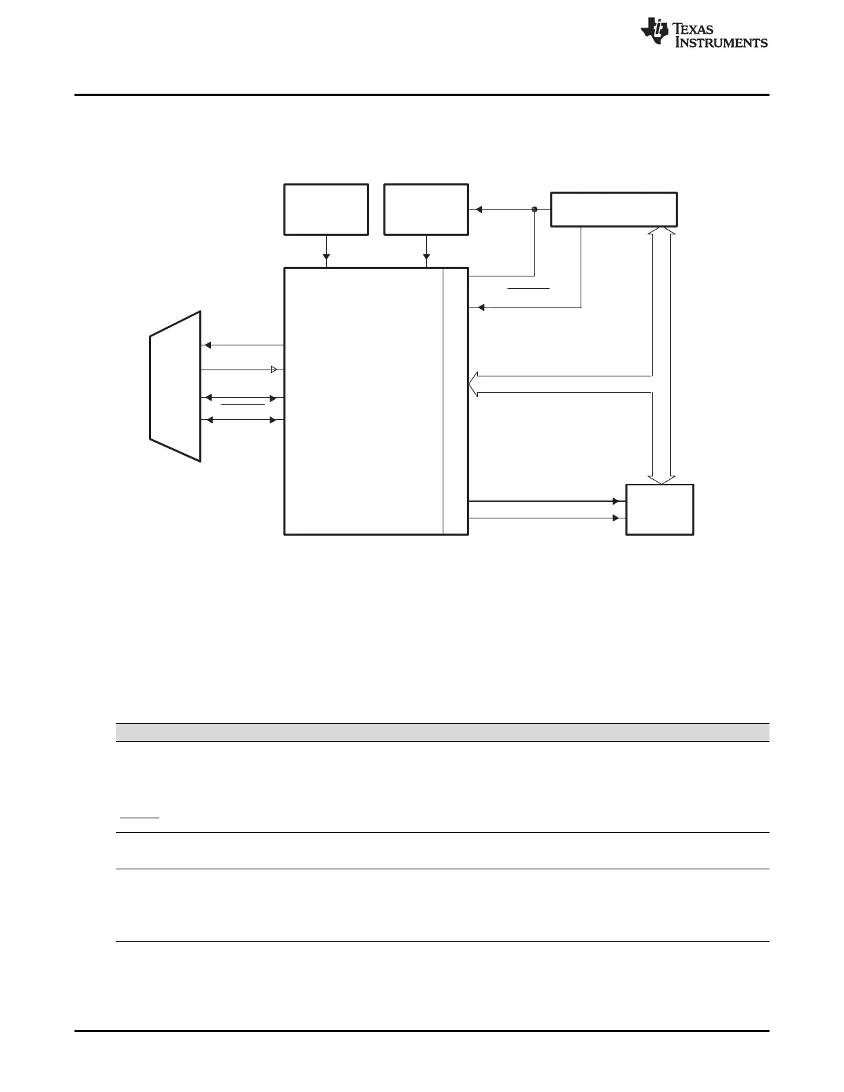
9.1.2 Block Diagram
Figure 9-1 shows the SPI CPU interfaces.
Figure 9-1. SPI CPU Interface
9.2 System-Level Integration
This section describes the various functionality that is applicable to the device integration. These features
require configuration of other modules in the device that are not within the scope of this chapter.
9.2.1 SPI Module Signals
Table 9-1 classifies and provides a summary of the SPI module signals.
Table 9-1. SPI Module Signal Summary
Signal Name Description
External Signals
SPICLK SPI clock
SPISIMO SPI slave in, master out
SPISOMI SPI slave out, master in
SPISTE SPI slave transmit enable
Control
SPI Clock Rate LSPCLK
Interrupt Signals
SPIINT/SPIRXINT Transmit interrupt/ Receive Interrupt in non FIFO mode (referred to as SPIINT)
Receive interrupt in FIFO mode
SPITXINT Transmit interrupt in FIFO mode
 Loading...