www.ti.com
McBSP Registers
767
SPRUI07–March 2020
Submit Documentation Feedback
Copyright © 2020, Texas Instruments Incorporated
Multichannel Buffered Serial Port (McBSP)
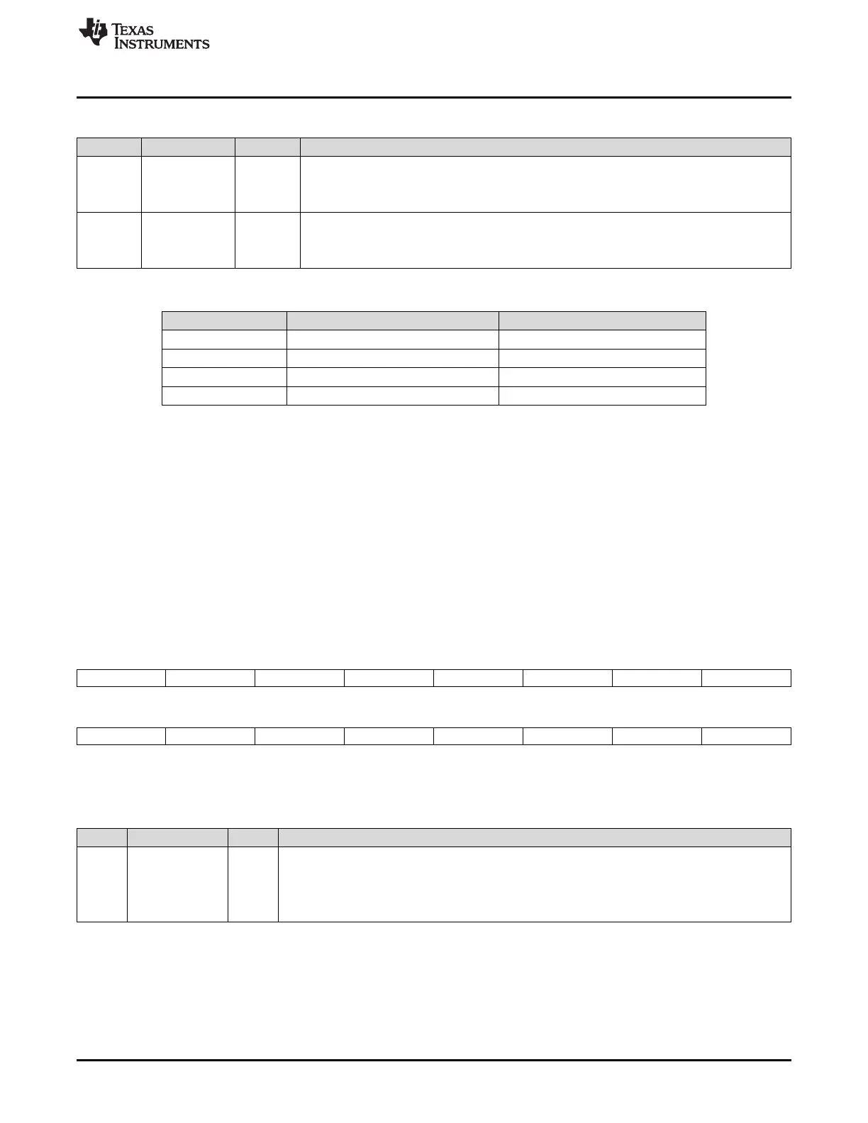
Table 12-91. Pin Control Register (PCR) Field Descriptions (continued)
Bit Field Value Description
1 CLKXP Transmit clock polarity bit. CLKXP determines the polarity of CLKX as seen on the MCLKX pin.
0 Transmit data is sampled on the rising edge of CLKX.
1 Transmit data is sampled on the falling edge of CLKX.
0 CLKRP Receive clock polarity bit. CLKRP determines the polarity of CLKR as seen on the MCLKR pin.
0 Receive data is sampled on the falling edge of MCLKR.
1 Receive data is sampled on the rising edge of MCLKR.
Table 12-92. Pin Configuration
Pin Selected as Output When … Selected as Input When …
CLKX CLKXM = 1 CLKXM = 0
FSX FSXM = 1 FSXM = 0
CLKR CLKRM = 1 CLKRM = 0
FSR FSRM = 1 FSRM = 0
12.15.10 Receive Channel Enable Registers (RCERA, RCERB, RCERC, RCERD, RCERE,
RCERF, RCERG, RCERH)
Each McBSP has eight receive channel enable registers of the format shown in Figure 12-80. There is
one enable register for each of the receive partitions: A, B, C, D, E, F, G, and H. Table 12-93 provides a
summary description that applies to any bit x of a receive channel enable register.
These memory-mapped registers are only used when the receiver is configured to allow individual
enabling and disabling of the channels (RMCM = 1). For more details about the way these registers are
used, see Section 12.15.10.1.
The receive channel enable registers (RCERA...RCERH) are shown in Figure 12-80 and described in
Table 12-93.
Figure 12-80. Receive Channel Enable Registers (RCERA...RCERH)
15 14 13 12 11 10 9 8
RCE15 RCE14 RCE13 RCE12 RCE11 RCE10 RCE9 RCE8
R/W-0 R/W-0 R/W-0 R/W-0 R/W-0 R/W-0 R/W-0 R/W-0
7 6 5 4 3 2 1 0
RCE7 RCE6 RCE5 RCE4 RCE3 RCE2 RCE1 RCE0
R/W-0 R/W-0 R/W-0 R/W-0 R/W-0 R/W-0 R/W-0 R/W-0
LEGEND: R/W = Read/Write; R = Read only; -n = value after reset
Table 12-93. Receive Channel Enable Registers (RCERA...RCERH) Field Descriptions
Bit Field Value Description
15-0 RCEx Receive channel enable bit.
For receive multichannel selection mode (RMCM = 1):
0 Disable the channel that is mapped to RCEx.
1 Enable the channel that is mapped to RCEx.
12.15.10.1 RCERs Used in the Receive Multichannel Selection Mode
For multichannel selection operation, the assignment of channels to the RCERs depends on whether 32
or 128 channels are individually selectable, as defined by the RMCME bit. For each of these two cases,
Table 12-94 shows which block of channels is assigned to each of the RCERs used. For each RCER, the
table shows which channel is assigned to each of the bits.
 Loading...