PLL
XCLKIN
SH clock/
pulse
No PLL
HISPCP
HSPCLK
ADCLKPS
CPS ADCCLK
ACQ_PS
ADCENCLK
PCLKCR[3]
F
clk
4-bit clock
divider
(x1, 1/2, ... 1/30)
HSPCLK
ADCTRL3[4-1]
(ADCLKPS[3-0])
x1/2
x1
ADCTRL1[7]=1
(CPS=1)
ADCTRL1[7]=0
(CPS=0)
SOC pulse
generator
S/H clock
pulse
ADCCLK
ADCTRL1[11-8]
(ACQ_PS[3-0])
ADC Circuit
www.ti.com
448
SPRUI07–March 2020
Submit Documentation Feedback
Copyright © 2020, Texas Instruments Incorporated
Analog-to-Digital Converter (ADC)
7.2 ADC Circuit
The following sub-sections describe the physical implementation of the ADC circuit. Topics that are
covered include:
• Clocking
• Sample and Hold Circuitry
• Reference Selection
• Power Modes and Sequencing
• Calibration and Offset Correction
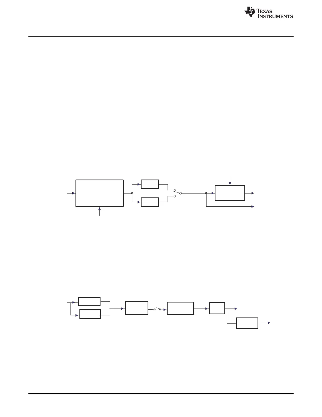
7.2.1 ADC Clocking and Sample Rate Calculations
The peripheral clock HSPCLK is divided down by the ADCCLKPS[3:0] bits of the ADCTRL3 register. An
extra divide-by-two is provided via the CPS bit of the ADCTRL1 register. In addition, the ADC can be
tailored to accommodate variations in source impedances by widening the sampling/acquisition period.
This is controlled by the ACQ_PS[3:0] bits in the ADCTRL1 register. These bits do not affect the
conversion portion of the S/H and conversion process, but do extend the length of time in which the
sampling portion takes by extending the start of the conversion pulse. See Figure 7-2.
Figure 7-2. ADC Core Clock and Sample-and-Hold (S/H) Clock
NOTE: See register bit definition for clock divider ratio and S/H pulse control. S/H pulse width determines the size of
acquisition window (the time period for which sampling switch is closed).
The ADC module has several prescaler stages to generate any desired ADC operating clock speed.
Figure 7-3 defines the clock selection stages that feed the ADC module. Table 7-1 gives two example
settings and shows both the effective sustained sampling rate and the sample and hold window time for
those settings in both sequential sampling mode (SMODE_SEL = 0) and simultaneous sampling mode
(SMODE_SEL = 1).
Figure 7-3. Clock Chain to the ADC
 Loading...