EPWM1SYNCO
ePWM1
EPWM1SYNCI
GPIO
MUX
SYNCI
eCAP1
EPWM2SYNCI
ePWM2
EPWM2SYNCO
EPWM3SYNCO
ePWM3
EPWM3SYNCI
EPWM4SYNCI
ePWM4
EPWM4SYNCO
EPWM5SYNCO
ePWM5
EPWM5SYNCI
ePWM6
EPWM6SYNCI
eCAP4
EPWM7SYNCI
ePWM7
EPWM7SYNCO
EPWM8SYNCI
ePWM8
EPWM8SYNCO
EPWM9SYNCI
ePWM9
ePWM Submodules
www.ti.com
232
SPRUI07–March 2020
Submit Documentation Feedback
Copyright © 2020, Texas Instruments Incorporated
Enhanced Pulse Width Modulator (ePWM) Module
memory address goes directly to the active register.
3.2.2.3.2 Time-Base Clock Synchronization
The TBCLKSYNC bit in the peripheral clock enable registers allows all users to globally synchronize all
enabled ePWM modules to the time-base clock (TBCLK). When set, all enabled ePWM module clocks are
started with the first rising edge of TBCLK aligned. For perfectly synchronized TBCLKs, the prescalers for
each ePWM module must be set identically.
The proper procedure for enabling ePWM clocks is as follows:
1. Enable ePWM module clocks in the PCLKCRx register
2. Set TBCLKSYNC= 0
3. Configure ePWM modules
4. Set TBCLKSYNC=1
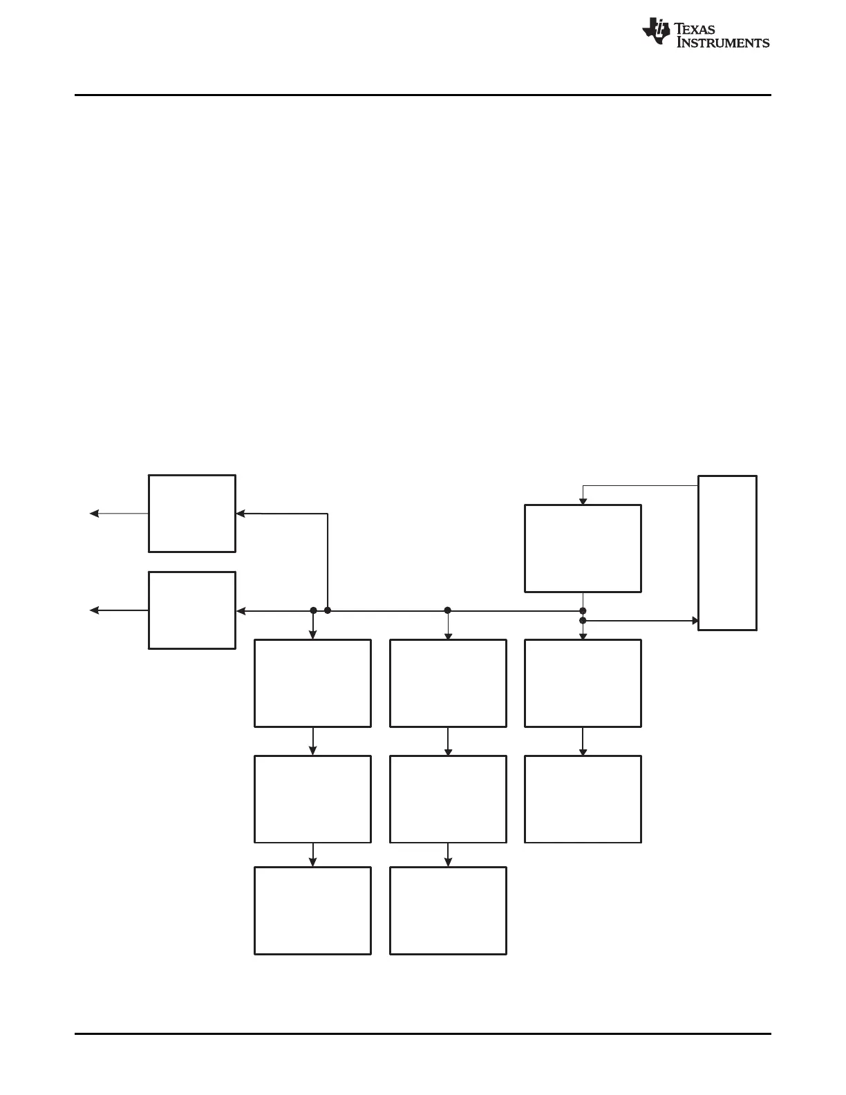
3.2.2.3.3 Time-Base Counter Synchronization
A time-base synchronization scheme connects all of the ePWM modules on a device. Each ePWM
module has a synchronization input (EPWMxSYNCI) and a synchronization output (EPWMxSYNCO). The
input synchronization for the first instance (ePWM1) comes from an external pin. The synchronization
connections for the remaining ePWM modules are shown in Figure 3-7
Figure 3-7. Time-Base Counter Synchronization Scheme
 Loading...