Reset InitBoot
SelectBootMode
Call ADC_cal
SelectXINTFx32
ConfigureZone6
ExitBoot
Jumpto
0x100000
Execute
Code
Reset InitBoot
SelectBootMode
Call ADC_cal
SelectXINTFx16
ConfigureZone6
ExitBoot
Jumpto
0x100000
Execute
Code
Bootloader Features
www.ti.com
178
SPRUI07–March 2020
Submit Documentation Feedback
Copyright © 2020, Texas Instruments Incorporated
Boot ROM
• Jump to XINTF Zone 6 Configured for 16-bit Data
The boot ROM configures XINTF zone 6 for 16 bit wide memory, maximum wait states, and sample
XREADY in asynchronous mode. This is the default values list after reset:
– XTIMCLK = ½ SYSCLKOUT
– XCLKOUT = ½ XTIMCLK
– XRDLEAD = XWRLEAD = 3
– XRDACTIVE = XWRACTIVE = 7
– XRDTRAIL = XWRACTIVE = 3
– XSIZE = 16-bit wide
– X2TIMING = 1. Timing values are 2:1.
– USEREADY = 1, READYMODE = 1 (XREADY sampled asynchronous mode)
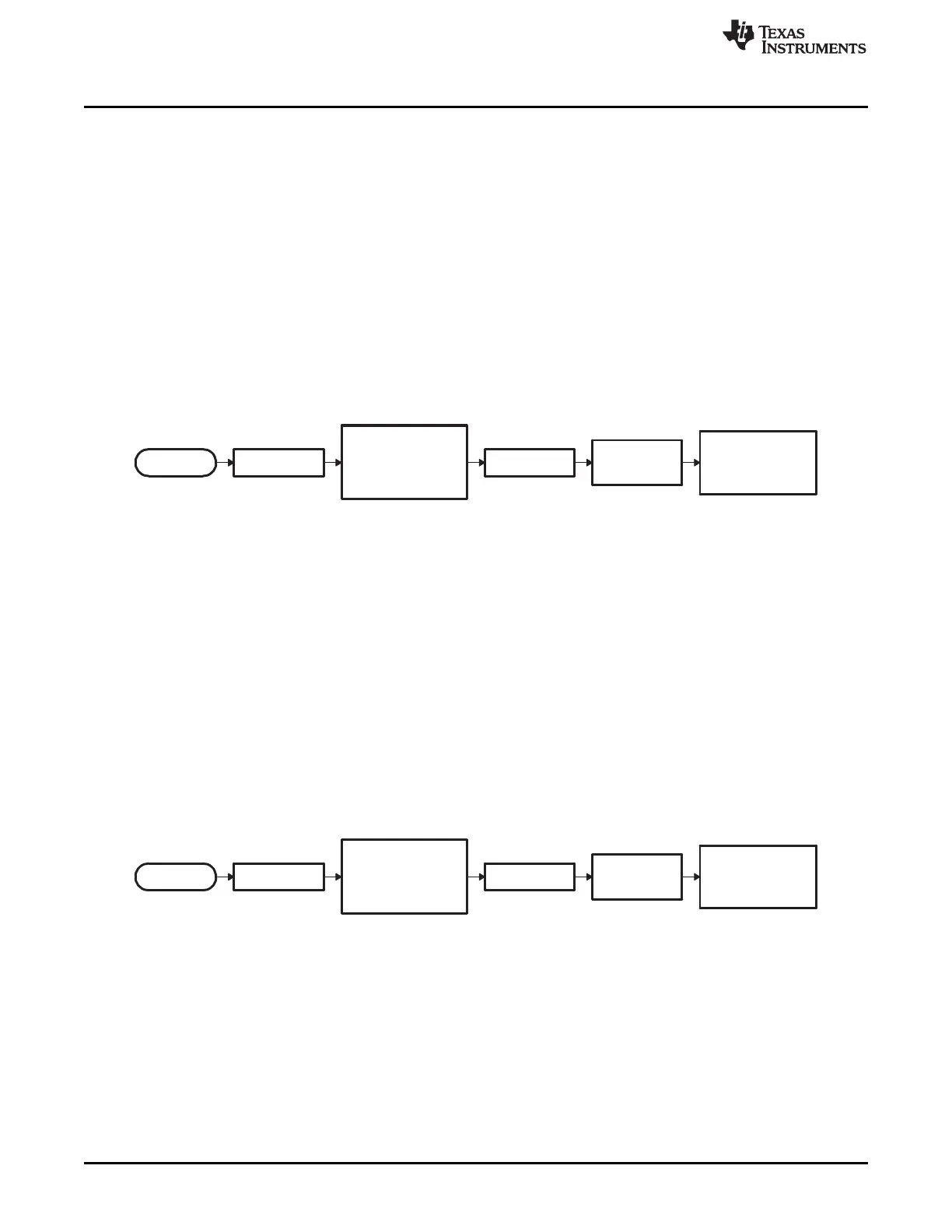
The boot ROM will then jump to the first location within zone 6 at address 0x10 0000.
Figure 2-9. Flow Diagram of Jump to XINTF x16
• Jump to XINTF Zone 6 Configured for 32-bit Data
In this mode, the boot ROM configures XINTF zone 6 for 32-bit wide memory, maximum wait states,
and sample XREADY in asynchronous mode. This is the default mode after reset except the bus width
is x32. The boot ROM will then jump to the first location within zone 6 at address 0x10 0000.
– XTIMCLK = ½ SYSCLKOUT
– XCLKOUT = ½ XTIMCLK
– XRDLEAD = XWRLEAD = 3
– XRDACTIVE = XWRACTIVE = 7
– XRDTRAIL = XWRACTIVE = 3
– XSIZE = 32-bit wide
– X2TIMING = 1. Timing values are 2:1.
– USEREADY = 1, READYMODE = 1 (XREADY sampled asynchronous mode)
Figure 2-10. Flow Diagram of Jump to XINTF x32
The following boot modes call a boot load routine that loads a data stream from the peripheral into
memory:
• Standard serial boot mode (SCI-A)
In this mode, the boot ROM will load code to be executed into on-chip memory via the SCI-A port.
• SPI EEPROM or Flash boot mode (SPI-A)
In this mode, the boot ROM will load code and data into on-chip memory from an external SPI
EEPROM or SPI flash via the SPI-A port.
 Loading...