Master Clock period (Tmst)
=
I2C Module Clock (Fmod)
[ (ICCH + d) + (ICCL + d) ]
SCL
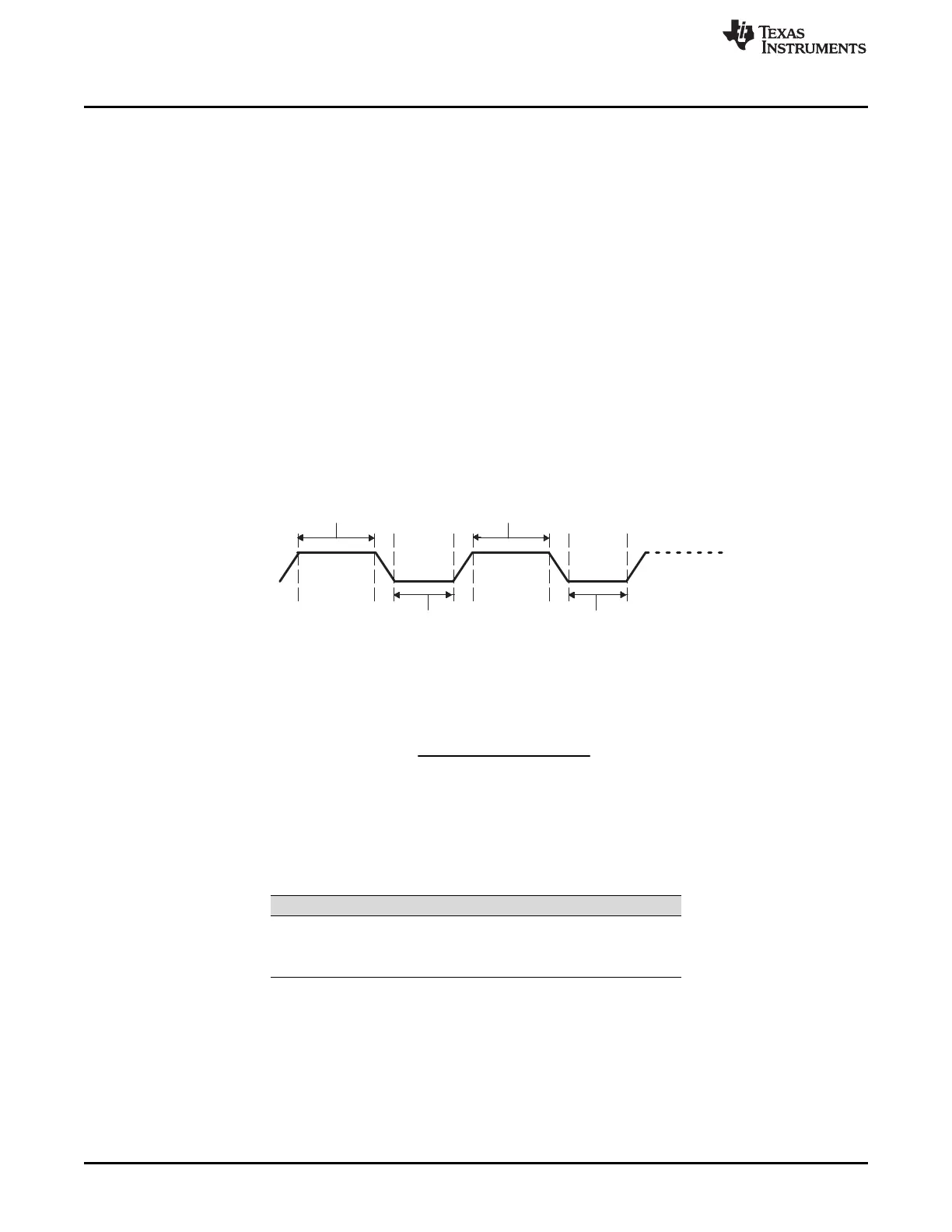
High-time duration:
Tmod × (ICCH + d)
High-time duration:
Tmod × (ICCH + d)
Low-time duration:
Tmod × (ICCL + d)
Low-time duration:
Tmod × (ICCL + d)
Introduction
www.ti.com
620
SPRUI07–March 2020
Submit Documentation Feedback
Copyright © 2020, Texas Instruments Incorporated
Inter-Integrated Circuit Module (I2C)
The prescaler must be initialized only while the I2C module is in the reset state (IRS = 0 in I2CMDR). The
prescaled frequency takes effect only when IRS is changed to 1. Changing the IPSC value while IRS = 1
has no effect.
The master clock appears on the SCL pin when the I2C module is configured to be a master on the I2C
bus. This clock controls the timing of communication between the I2C module and a slave. As shown in
Figure 11-3, a second clock divider in the I2C module divides down the module clock to produce the
master clock. The clock divider uses the ICCL value of I2CCLKL to divide down the low portion of the
module clock signal and uses the ICCH value of I2CCLKH to divide down the high portion of the module
clock signal. See Section 11.1.5 for the master clock frequency equation.
11.1.5 I2C Clock Divider Registers (I2CCLKL and I2CCLKH)
As explained in Section 11.1.4, when the I2C module is a master, the I2C module clock is divided down
further to use as the master clock on the SCL pin. As shown in Figure 11-4, the shape of the master clock
depends on two divide-down values:
• ICCL in I2CCLKL. For each master clock cycle, ICCL determines the amount of time the signal is low.
• ICCH in I2CCKLH. For each master clock cycle, ICCH determines the amount of time the signal is
high.
Figure 11-4. The Roles of the Clock Divide-Down Values (ICCL and ICCH)
11.1.5.1 Formula for the Master Clock Period
The master clock period (Tmst) is a multiple of the period of the I2C Module Clock (Tmod):
where d depends on the divide-down value IPSC, as shown in Table 11-1. IPSC is described in the
I2CPSC register.
Table 11-1. Dependency of Delay d on the Divide-Down
Value IPSC
IPSC d
0 7
1 6
Greater than 1 5
11.2 Configuring Device Pins
The GPIO mux registers must be configured to connect this peripheral to the device pins.
Some IO functionality is defined by GPIO register settings independent of this peripheral. For input
signals, the GPIO input qualification should be set to asynchronous mode by setting the appropriate
GPxQSELn register bits to 11b. The internal pullups can be configured in the GPyPUD register.
See the GPIO chapter for more details on GPIO mux and settings.
 Loading...