www.ti.com
eQEP Registers
439
SPRUI07–March 2020
Submit Documentation Feedback
Copyright © 2020, Texas Instruments Incorporated
Enhanced Quadrature Encoder Pulse (eQEP)
6.10.2.20 QEPSTS Register (Offset = 1Ch) [reset = 0h]
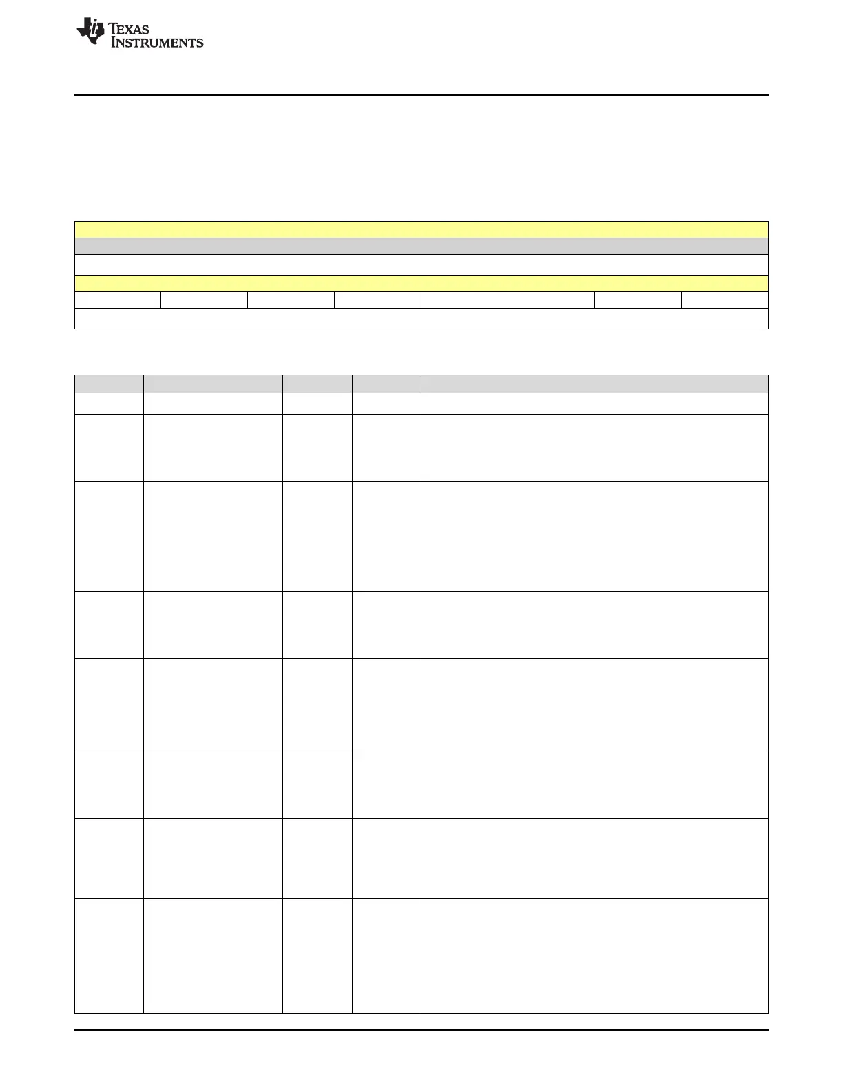
QEPSTS is shown in Figure 6-40 and described in Table 6-25.
Return to the Summary Table.
QEP Status
Figure 6-40. QEPSTS Register
15 14 13 12 11 10 9 8
RESERVED
R-0h
7 6 5 4 3 2 1 0
UPEVNT FIDF QDF QDLF COEF CDEF FIMF PCEF
R/W-0h R-0h R-0h R-0h R/W-0h R/W-0h R/W-0h R-0h
Table 6-25. QEPSTS Register Field Descriptions
Bit Field Type Reset Description
15-8 RESERVED R 0h
Reserved
7 UPEVNT R/W 0h
Unit position event flag
Reset type: SYSRSn
0h (R/W) = No unit position event detected
1h (R/W) = Unit position event detected. Write 1 to clear
6 FIDF R 0h
Direction on the first index marker
Status of the direction is latched on the first index event marker.
Reset type: SYSRSn
0h (R/W) = Counter-clockwise rotation (or reverse movement) on
the first index event
1h (R/W) = Clockwise rotation (or forward movement) on the first
index event
5 QDF R 0h
Quadrature direction flag
Reset type: SYSRSn
0h (R/W) = Counter-clockwise rotation (or reverse movement)
1h (R/W) = Clockwise rotation (or forward movement)
4 QDLF R 0h
eQEP direction latch flag
Reset type: SYSRSn
0h (R/W) = Counter-clockwise rotation (or reverse movement) on
index event marker
1h (R/W) = Clockwise rotation (or forward movement) on index
event marker
3 COEF R/W 0h
Capture overflow error flag
Reset type: SYSRSn
0h (R/W) = Overflow has not occurred.
1h (R/W) = Overflow occurred in eQEP Capture timer (QEPCTMR).
2 CDEF R/W 0h
Capture direction error flag
Reset type: SYSRSn
0h (R/W) = Capture direction error has not occurred.
1h (R/W) = Direction change occurred between the capture
position event.
1 FIMF R/W 0h
First index marker flag
Note: Once this flag has been set, if the flag is cleared the flag will
not be set again until the module is reset by a peripheral or system
reset.
Reset type: SYSRSn
0h (R/W) = First index pulse has not occurred.
1h (R/W) = Set by first occurrence of index pulse.

 Loading...