Register Descriptions
www.ti.com
520
SPRUI07–March 2020
Submit Documentation Feedback
Copyright © 2020, Texas Instruments Incorporated
Direct Memory Access (DMA) Module
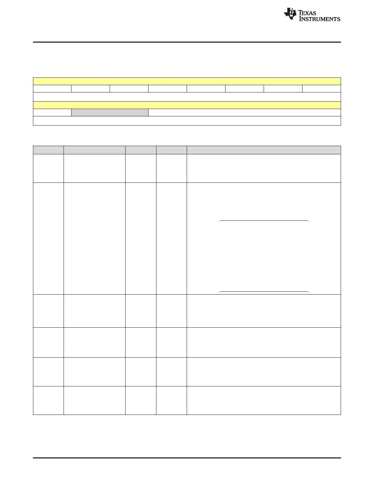
8.9.6 MODE Register (Offset = 1020h + [i * E3h]) [reset = 0h]
MODE is shown in Figure 8-13 and described in Table 8-8.
Figure 8-13. MODE Register
15 14 13 12 11 10 9 8
CHINTE DATASIZE SYNCSEL SYNCE CONTINUOUS ONESHOT CHINTMODE PERINTE
R/W-0h R/W-0h R/W-0h R/W-0h R/W-0h R/W-0h R/W-0h R/W-0h
7 6 5 4 3 2 1 0
OVRINTE RESERVED PERINTSEL
R/W-0h R-0h R/W-0h
(1)
You should write to the MODE register only when the RUNSTS bit is 0 (DMA channel stopped or halted). Typically though, the values
should only be configured when the channel is stopped.
(2)
The ADCSYNC only works when the sequencer override bit is set in the ADC sequencer control registers.
(3)
The overflow interrupt is ORed together with the DMACH interrupt as shown in Figure 8-7.
Table 8-8. MODE Register Field Descriptions
(1)(2)(3)
Bit Field Type Reset Description
15 CHINTE R/W 0h
Channel Interrupt Enable Bit: This bit enables/disables the respective
DMA channel interrupt to the CPU (via the PIE).
0h = Interrupt disabled
1h = Interrupt enabled
14 DATASIZE R/W 0h Data Size Mode Bit: This bit selects if the DMA channel transfers
16-bits or
32-bits of data at a time.
0h = 16-bit data transfer size
1h = 32-bit data transfer size
NOTE: Regardless of the value of this bit
all of the registers in the DMA refer
to 16-bit words. The only effect this
bit causes is whether the databus
width is 16 or 32 bits.
It is up to you to configure the
pointer step increment and size to
accommodate 32-bit data transfers.
See section Section 8.6 for details.
13 SYNCSEL R/W 0h Sync Mode Select Bit: This bit selects if the SRC or DST wrap
counters are controlled by the sync function (if enabled by SYNCE
bit).
0h = SRC wrap counter controlled
1h = DST wrap counter controlled
12 SYNCE R/W 0h Sync Enable Bit: If this bit is set to 1, the ADCSYNC signal is
recognized if selected by the PERINTSEL bit field.
This sync signal is used to synchronize ADC interrupt event triggers
to the DMA wrap counter.
If this bit is 0 then the ADCSYNC event is ignored.
11 CONTINUOUS R/W 0h
Continuous Mode Bit:
0h = DMA stops and clears the RUNSTS bit to 0.
1h = DMA re-initializes when TRANSFER_COUNT is zero and waits
for the next interrupt event trigger.
10 ONESHOT R/W 0h
One Shot Mode Bit:
0h = only one burst transfer is performed per event trigger.
1h = subsequent burst transfers occur without additional event
triggers after the first event trigger.
 Loading...