SPI Registers
www.ti.com
570
SPRUI07–March 2020
Submit Documentation Feedback
Copyright © 2020, Texas Instruments Incorporated
Serial Peripheral Interface (SPI)
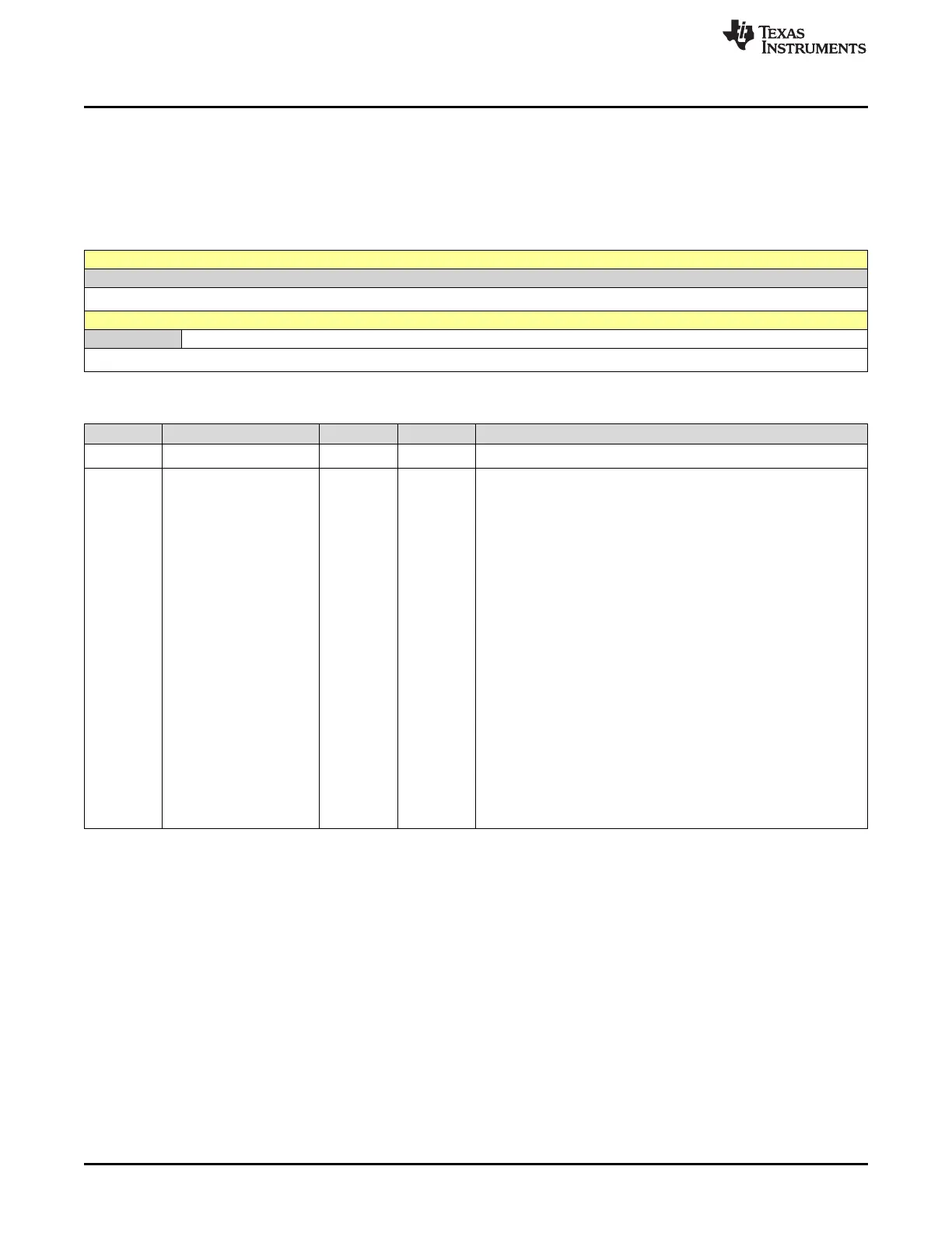
9.5.2.4 SPIBRR Register (Offset = 4h) [reset = 0h]
SPIBRR is shown in Figure 9-11 and described in Table 9-10.
Return to the Summary Table.
SPIBRR contains the bits used for baud-rate selection.
Figure 9-11. SPIBRR Register
15 14 13 12 11 10 9 8
RESERVED
R-0h
7 6 5 4 3 2 1 0
RESERVED SPI_BIT_RATE
R-0h R/W-0h
Table 9-10. SPIBRR Register Field Descriptions
Bit Field Type Reset Description
15-7 RESERVED R 0h
Reserved
6-0 SPI_BIT_RATE R/W 0h
SPI Baud Rate Control
These bits determine the bit transfer rate if the SPI is the network
SPI BIT RATE 0 master. There are 125 data-transfer rates (each a
function of the CPU clock, LSPCLK) that can be selected. One data
bit is shifted per SPICLK cycle. (SPICLK is the baud rate clock
output on the SPICLK pin.)
If the SPI is a network slave, the module receives a clock on the
SPICLK pin from the network master. Therefore, these bits have no
effect on the SPICLK signal. The frequency of the input clock from
the master should not exceed the slave SPI's LSPCLK signal divided
by 4.
In master mode, the SPI clock is generated by the SPI and is output
on the SPICLK pin. The SPI baud rates are determined by the
following formula:
For SPIBRR = 3 to 127: SPI Baud Rate = LSPCLK / (SPIBRR + 1)
For SPIBRR = 0, 1, or 2: SPI Baud Rate = LSPCLK / 4
Reset type: SYSRSn
3h (R/W) = SPI Baud Rate = LSPCLK/4
4h (R/W) = SPI Baud Rate = LSPCLK/5
7Eh (R/W) = SPI Baud Rate = LSPCLK/127
7Fh (R/W) = SPI Baud Rate = LSPCLK/128
 Loading...