I2CDRR I2CRSR
0
1
I2CSAR
I2COAR
0
1
I2CDXR
I2CXSR
0
1
0
0
DLB
SCL_IN
SCL_OUT
Address/data
To internal I
2
C logic
From internal I
2
C logic
To internal
I2
C logic
To CPU
From CPU
From CPU
From CPU
SCL
SDA
I
2
C module
DLB
DLB
Interrupt Requests Generated by the I2C Module
www.ti.com
628
SPRUI07–March 2020
Submit Documentation Feedback
Copyright © 2020, Texas Instruments Incorporated
Inter-Integrated Circuit Module (I2C)
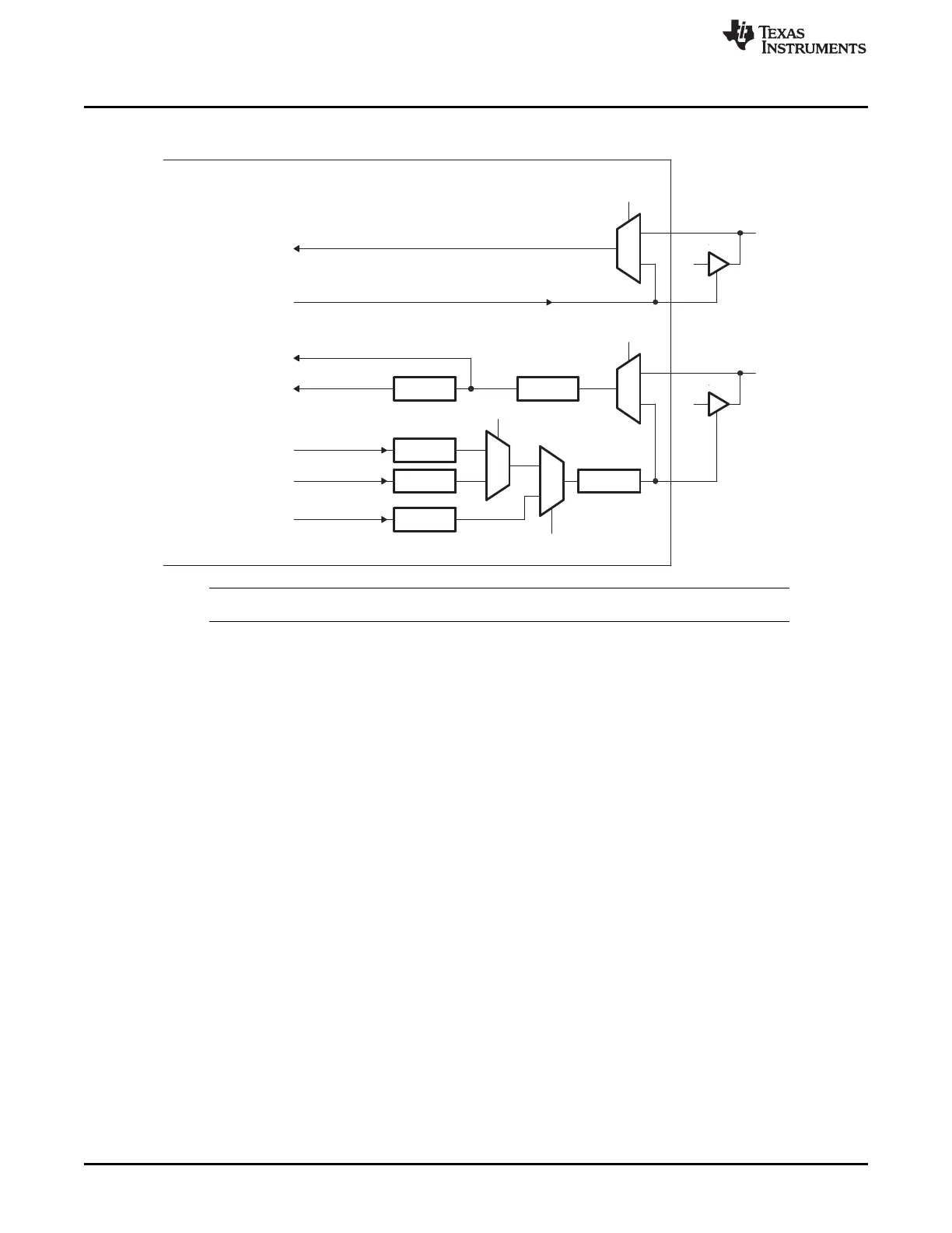
Figure 11-14. Pin Diagram Showing the Effects of the Digital Loopback Mode (DLB) Bit
NOTE: The free data format (I2CMDR.FDF = 1) is not supported in digital loopback mode.
11.4 Interrupt Requests Generated by the I2C Module
Each I2C module can generate two CPU interrupts.
1. Basic I2C interrupt: Possible basic I2C interrupt sources which can trigger this interrupt are described
in Section 11.4.1.
2. I2C FIFO interrupt: Possible I2C FIFO interrupt sources which can trigger this interrupt are described in
Section 11.4.2
11.4.1 Basic I2C Interrupt Requests
The I2C module generates the interrupt requests described in Table 11-6. As shown in Figure 11-15, all
requests are multiplexed through an arbiter to a single I2C interrupt request to the CPU. Each interrupt
request has a flag bit in the status register (I2CSTR) and an enable bit in the interrupt enable register
(I2CIER). When one of the specified events occurs, its flag bit is set. If the corresponding enable bit is 0,
the interrupt request is blocked. If the enable bit is 1, the request is forwarded to the CPU as an I2C
interrupt.
The I2C interrupt is one of the maskable interrupts of the CPU. As with any maskable interrupt request, if
it is properly enabled in the CPU, the CPU executes the corresponding interrupt service routine
(I2CINT1A_ISR). The I2CINT1A_ISR for the I2C interrupt can determine the interrupt source by reading
the interrupt source register, I2CISRC. Then the I2CINT1A_ISR can branch to the appropriate subroutine.
After the CPU reads I2CISRC, the following events occur:
1. The flag for the source interrupt is cleared in I2CSTR. Exception: The ARDY, RRDY, and XRDY bits in
I2CSTR are not cleared when I2CISRC is read. To clear one of these bits, write a 1 to it.
2. The arbiter determines which of the remaining interrupt requests has the highest priority, writes the
code for that interrupt to I2CISRC, and forwards the interrupt request to the CPU.
 Loading...