www.ti.com
I2C Registers
643
SPRUI07–March 2020
Submit Documentation Feedback
Copyright © 2020, Texas Instruments Incorporated
Inter-Integrated Circuit Module (I2C)
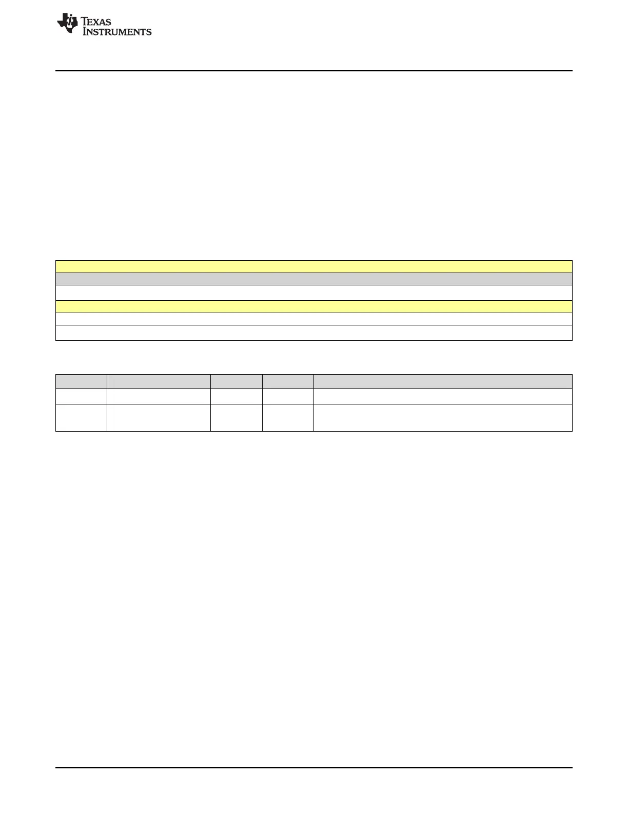
11.6.2.7 I2CDRR Register (Offset = 6h) [reset = 0h]
I2CDRR is shown in Figure 11-24 and described in Table 11-16.
Return to the Summary Table.
I2CDRR is a 16-bit register used by the CPU to read received data. The I2C module can receive a data
byte with 1 to 8 bits. The number of bits is selected with the bit count (BC) bits in I2CMDR. One bit at a
time is shifted in from the SDA pin to the receive shift register (I2CRSR). When a complete data byte has
been received, the I2C module copies the data byte from I2CRSR to I2CDRR. The CPU cannot access
I2CRSR directly.
If a data byte with fewer than 8 bits is in I2CDRR, the data value is right-justified, and the other bits of
I2CDRR(7-0) are undefined. For example, if BC = 011 (3-bit data size), the receive data is in I2CDRR(2-
0), and the content of I2CDRR(7-3) is undefined.
When in the receive FIFO mode, the I2CDRR register acts as the receive FIFO buffer.
Figure 11-24. I2CDRR Register
15 14 13 12 11 10 9 8
RESERVED
R-0h
7 6 5 4 3 2 1 0
DATA
R-0h
Table 11-16. I2CDRR Register Field Descriptions
Bit Field Type Reset Description
15-8 RESERVED R 0h
Reserved
7-0 DATA R 0h
Receive data
Reset type: SYSRSn
 Loading...