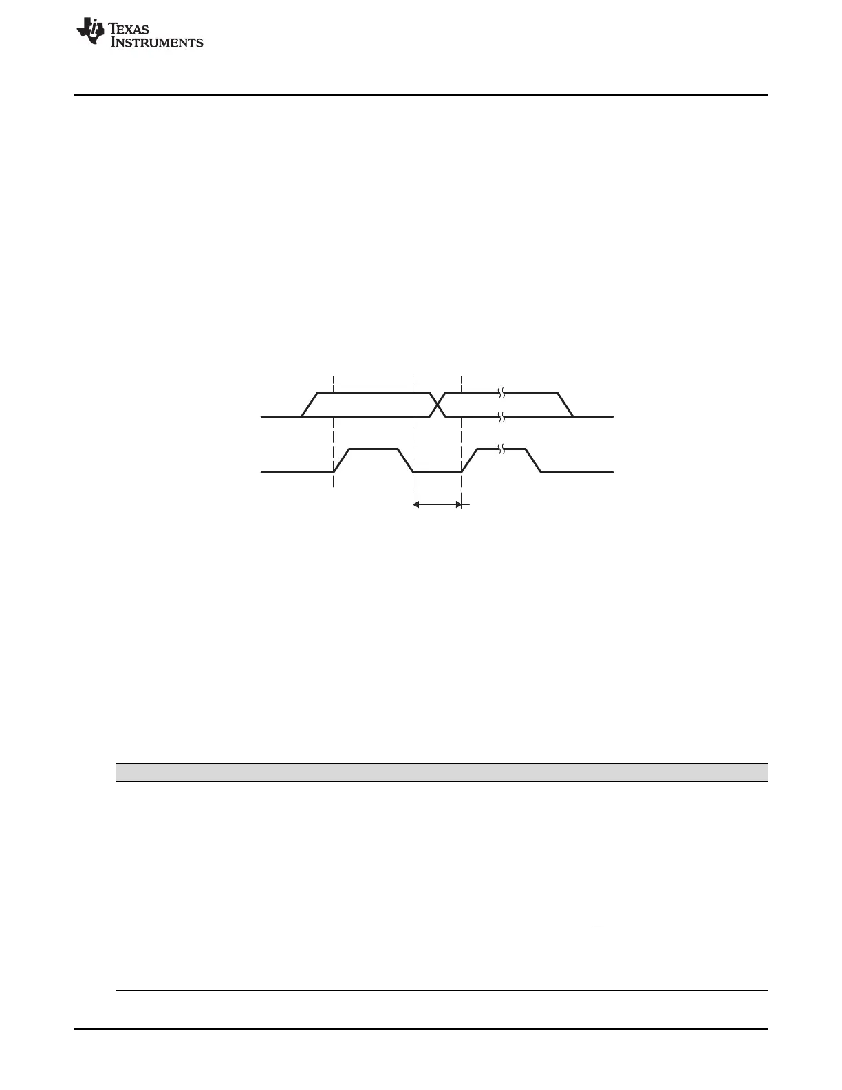
Data line
stable data
Change of data
allowed
SDA
SCL
www.ti.com
I2C Module Operational Details
621
SPRUI07–March 2020
Submit Documentation Feedback
Copyright © 2020, Texas Instruments Incorporated
Inter-Integrated Circuit Module (I2C)
11.3 I2C Module Operational Details
This section provides an overview of the I2C bus protocol and how it is implemented.
11.3.1 Input and Output Voltage Levels
One clock pulse is generated by the master device for each data bit transferred. Due to a variety of
different technology devices that can be connected to the I2C bus, the levels of logic 0 (low) and logic 1
(high) are not fixed and depend on the associated level of V
DD
. For details, see the data manual for your
particular device.
11.3.2 Data Validity
The data on SDA must be stable during the high period of the clock (see Figure 11-5). The high or low
state of the data line, SDA, should change only when the clock signal on SCL is low.
Figure 11-5. Bit Transfer on the I2C bus
11.3.3 Operating Modes
The I2C module has four basic operating modes to support data transfers as a master and as a slave.
See Table 11-2 for the names and descriptions of the modes.
If the I2C module is a master, it begins as a master-transmitter and typically transmits an address for a
particular slave. When giving data to the slave, the I2C module must remain a master-transmitter. To
receive data from a slave, the I2C module must be changed to the master-receiver mode.
If the I2C module is a slave, it begins as a slave-receiver and typically sends acknowledgment when it
recognizes its slave address from a master. If the master will be sending data to the I2C module, the
module must remain a slave-receiver. If the master has requested data from the I2C module, the module
must be changed to the slave-transmitter mode.
Table 11-2. Operating Modes of the I2C Module
Operating Mode Description
Slave-receiver modes The I2C module is a slave and receives data from a master.
All slaves begin in this mode. In this mode, serial data bits received on SDA are shifted in with
the clock pulses that are generated by the master. As a slave, the I2C module does not
generate the clock signal, but it can hold SCL low while the intervention of the device is
required (RSFULL = 1 in I2CSTR) after a byte has been received. See Section 11.3.7 for more
details.
Slave-transmitter mode The I2C module is a slave and transmits data to a master.
This mode can be entered only from the slave-receiver mode; the I2C module must first receive
a command from the master. When you are using any of the 7-bit/10-bit addressing formats,
the I2C module enters its slave-transmitter mode if the slave address byte is the same as its
own address (in I2COAR) and the master has transmitted R/W = 1. As a slave-transmitter, the
I2C module then shifts the serial data out on SDA with the clock pulses that are generated by
the master. While a slave, the I2C module does not generate the clock signal, but it can hold
SCL low while the intervention of the device is required (XSMT = 0 in I2CSTR) after a byte has
been transmitted. See Section 11.3.7 for more details.
 Loading...