INT12
MUX
INT11
INT2
INT1
CPU
(Enable)(Flag)
INTx
INTx.8
PIEIERx(8:1) PIEIFRx(8:1)
MUX
INTx.7
INTx.6
INTx.5
INTx.4
INTx.3
INTx.2
INTx.1
From
Peripherals or
External
Interrupts
(Enable) (Flag)
IER(12:1)IFR(12:1)
Global
Enable
INTM
1
0
PIEACKx
(Enable/Flag)
www.ti.com
Peripheral Interrupt Expansion (PIE)
139
SPRUI07–March 2020
Submit Documentation Feedback
Copyright © 2020, Texas Instruments Incorporated
System Control and Interrupts
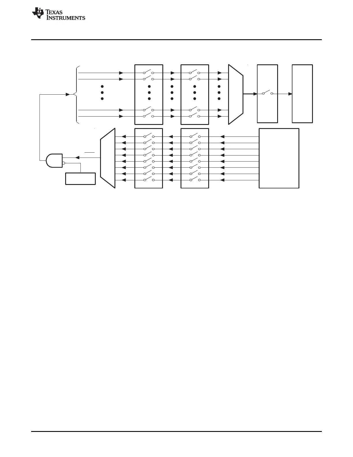
Figure 1-78. Overview: Multiplexing of Interrupts Using the PIE Block
• Peripheral Level
An interrupt-generating event occurs in a peripheral. The interrupt flag (IF) bit corresponding to that
event is set in a register for that particular peripheral.
If the corresponding interrupt enable (IE) bit is set, the peripheral generates an interrupt request to the
PIE controller. If the interrupt is not enabled at the peripheral level, then the IF remains set until
cleared by software. If the interrupt is enabled at a later time, and the interrupt flag is still set, the
interrupt request is asserted to the PIE.
Interrupt flags within the peripheral registers must be manually cleared. See the peripheral reference
guide for a specific peripheral for more information.
• PIE Level
The PIE block multiplexes eight peripheral and external pin interrupts into one CPU interrupt. These
interrupts are divided into 12 groups: PIE group 1 - PIE group 12. The interrupts within a group are
multiplexed into one CPU interrupt. For example, PIE group 1 is multiplexed into CPU interrupt 1
(INT1) while PIE group 12 is multiplexed into CPU interrupt 12 (INT12). Interrupt sources connected to
the remaining CPU interrupts are not multiplexed. For the nonmultiplexed interrupts, the PIE passes
the request directly to the CPU.
For multiplexed interrupt sources, each interrupt group in the PIE block has an associated flag register
(PIEIFRx) and enable (PIEIERx) register (x = PIE group 1 - PIE group 12). Each bit, referred to as y,
corresponds to one of the 8 MUXed interrupts within the group. Thus PIEIFRx.y and PIEIERx.y
correspond to interrupt y (y = 1-8) in PIE group x (x = 1-12). In addition, there is one acknowledge bit
(PIEACK) for every PIE interrupt group referred to as PIEACKx (x = 1-12). Figure 1-79 illustrates the
behavior of the PIE hardware under various PIEIFR and PIEIER register conditions.
Once the request is made to the PIE controller, the corresponding PIE interrupt flag (PIEIFRx.y) bit is
set. If the PIE interrupt enable (PIEIERx.y) bit is also set for the given interrupt then the PIE checks the
corresponding PIEACKx bit to determine if the CPU is ready for an interrupt from that group. If the
PIEACKx bit is clear for that group, then the PIE sends the interrupt request to the CPU. If PIEACKx is
set, then the PIE waits until it is cleared to send the request for INTx. See Section 1.6.3 for details.
• CPU Level
Once the request is sent to the CPU, the CPU level interrupt flag (IFR) bit corresponding to INTx is set.
After a flag has been latched in the IFR, the corresponding interrupt is not serviced until it is
appropriately enabled in the CPU interrupt enable (IER) register or the debug interrupt enable register
(DBGIER) and the global interrupt mask (INTM) bit.
 Loading...