APRD
TSCTR
FFFFFFFF
ACMP
0000000C
APWMx
(o/p pin)
On
time
Off−time
Period
1000h
500h
300h
Application of the APWM Mode
www.ti.com
368
SPRUI07–March 2020
Submit Documentation Feedback
Copyright © 2020, Texas Instruments Incorporated
Enhanced Capture (eCAP)
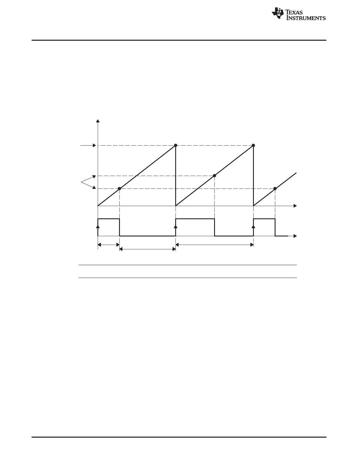
5.7 Application of the APWM Mode
In this example, the eCAP module is configured to operate as a PWM generator. Here, a very simple
single-channel PWM waveform is generated from the APWMx output pin. The PWM polarity is active high,
which means that the compare value (CAP2 reg is now a compare register) represents the on-time (high
level) of the period. Alternatively, if the APWMPOL bit is configured for active low, then the compare value
represents the off-time.
5.7.1 Example 1 - Simple PWM Generation (Independent Channel/s)
Figure 5-16. PWM Waveform Details of APWM Mode Operation
NOTE: Values are in hexadecimal (“h”) notation.
5.7.2 Example 2 - Multi-channel PWM Generation With Phase Control
In this example the Phase control feature of the APWM mode is used to control a 3 phase Interleaved
DC/DC converter topology. This topology requires each phase to be off-set by 120° from each other.
Hence if “Leg” 1 (controlled by APWM1) is the reference Leg (or phase), i.e. 0°, then Leg 2 need 120° off-
set and Leg 3 needs 240° off-set. The waveforms in Figure 5-17 show the timing relationship between
each of the phases (Legs). Note eCAP1 module is the Master and issues a sync out pulse to the slaves
(modules 2, 3) whenever TSCTR = Period value.
 Loading...