0000
FFFFh
TBPRD
TBCTR[0-15]
time
CTR = PRD
(SycnOut)
Master Module
Φ2
Phase = 120°
0000
FFFFh
TBPRD
TBCTR[0-15]
time
SyncIn
Slave Module
TBPHS
600 600
600 600
200
200
www.ti.com
Applications to Power Topologies
289
SPRUI07–March 2020
Submit Documentation Feedback
Copyright © 2020, Texas Instruments Incorporated
Enhanced Pulse Width Modulator (ePWM) Module
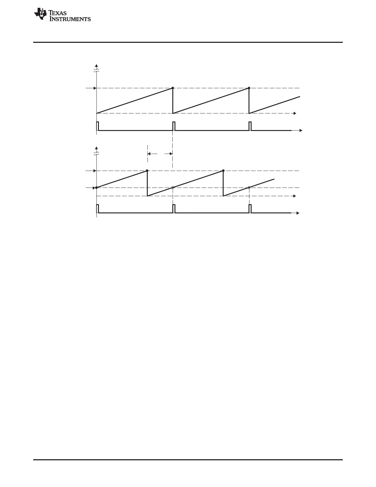
Figure 3-56. Timing Waveforms Associated With Phase Control Between 2 Modules
3.3.8 Controlling a 3-Phase Interleaved DC/DC Converter
A popular power topology that makes use of phase-offset between modules is shown in Figure 3-57. This
system uses three PWM modules, with module 1 configured as the master. To work, the phase
relationship between adjacent modules must be F = 120°. This is achieved by setting the slave TBPHS
registers 2 and 3 with values of 1/3 and 2/3 of the period value, respectively. For example, if the period
register is loaded with a value of 600 counts, then TBPHS (slave 2) = 200 and TBPHS (slave 3) = 400.
Both slave modules are synchronized to the master 1 module.
This concept can be extended to four or more phases, by setting the TBPHS values appropriately. The
following formula gives the TBPHS values for N phases:
TBPHS(N,M) = (TBPRD/N) x (M—1)
Where:
N = number of phases
M = PWM module number
For example, for the 3-phase case (N=3), TBPRD = 600,
TBPHS(3,2) = (600/3) x (2-1) = 200 (i.e., Phase value for Slave module 2)
TBPHS(3,3) = 400 (i.e., Phase value for Slave module 3)
Figure 3-58 shows the waveforms for the configuration in Figure 3-57.
 Loading...