I2C Registers
www.ti.com
646
SPRUI07–March 2020
Submit Documentation Feedback
Copyright © 2020, Texas Instruments Incorporated
Inter-Integrated Circuit Module (I2C)
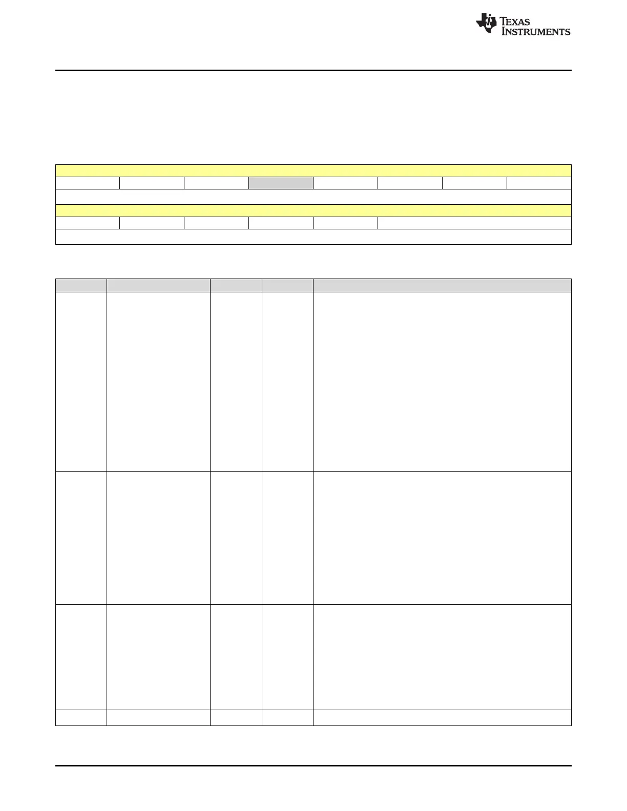
11.6.2.10 I2CMDR Register (Offset = 9h) [reset = 0h]
I2CMDR is shown in Figure 11-27 and described in Table 11-19.
Return to the Summary Table.
The I2C mode register (I2CMDR) is a 16-bit register that contains the control bits of the I2C module.
Figure 11-27. I2CMDR Register
15 14 13 12 11 10 9 8
NACKMOD FREE STT RESERVED STP MST TRX XA
R/W-0h R/W-0h R/W-0h R-0h R/W-0h R/W-0h R/W-0h R/W-0h
7 6 5 4 3 2 1 0
RM DLB IRS STB FDF BC
R/W-0h R/W-0h R/W-0h R/W-0h R/W-0h R/W-0h
Table 11-19. I2CMDR Register Field Descriptions
Bit Field Type Reset Description
15 NACKMOD R/W 0h
NACK mode bit. This bit is only applicable when the I2C module is
acting as a receiver.
Reset type: SYSRSn
0h (R/W) = In the slave-receiver mode: The I2C module sends an
acknowledge (ACK) bit to the transmitter during each acknowledge
cycle on the bus. The I2C module only sends a no-acknowledge
(NACK) bit if you set the NACKMOD bit.
In the master-receiver mode: The I2C module sends an ACK bit
during each acknowledge cycle until the internal data counter
counts down to 0. At that point, the I2C module sends a NACK bit
to the transmitter. To have a NACK bit sent earlier, you must set
the NACKMOD bit
1h (R/W) = In either slave-receiver or master-receiver mode: The
I2C module sends a NACK bit to the transmitter during the next
acknowledge cycle on the bus. Once the NACK bit has been sent,
NACKMOD is cleared.
Important: To send a NACK bit in the next acknowledge cycle, you
must set NACKMOD before the rising edge of the last data bit.
14 FREE R/W 0h
This bit controls the action taken by the I2C module when a
debugger breakpoint is encountered.
Reset type: SYSRSn
0h (R/W) = When I2C module is master:
If SCL is low when the breakpoint occurs, the I2C module stops
immediately and keeps driving SCL low, whether the I2C module is
the transmitter or the receiver. If SCL is high, the I2C module waits
until SCL becomes low and then stops.
When I2C module is slave:
A breakpoint forces the I2C module to stop when the current
transmission/reception is complete.
1h (R/W) = The I2C module runs free
that is, it continues to operate when a breakpoint occurs.
13 STT R/W 0h
START condition bit (only applicable when the I2C module is a
master). The RM, STT, and STP bits determine when the I2C
module starts and stops data transmissions (see Table 9-6). Note
that the STT and STP bits can be used to terminate the repeat
mode, and that this bit is not writable when IRS = 0.
Reset type: SYSRSn
0h (R/W) = In the master mode, STT is automatically cleared after
the START condition has been generated.
1h (R/W) = In the master mode, setting STT to 1 causes the I2C
module to generate a START condition on the I2C-bus
12 RESERVED R 0h
Reserved
 Loading...