u
PWM TSCTR
PWM
PWM
T CAP1 1 T
1
F
T
www.ti.com
Capture Mode Description
363
SPRUI07–March 2020
Submit Documentation Feedback
Copyright © 2020, Texas Instruments Incorporated
Enhanced Capture (eCAP)
The behavior of APWM active high mode (APWMPOL == 0) is as follows:
CMP = 0x00000000, output low for duration of period (0% duty)
CMP = 0x00000001, output high 1 cycle
CMP = 0x00000002, output high 2 cycles
CMP = PERIOD, output high except for 1 cycle (<100% duty)
CMP = PERIOD+1, output high for complete period (100% duty)
CMP > PERIOD+1, output high for complete period
The behavior of APWM active low mode (APWMPOL == 1) is as follows:
CMP = 0x00000000, output high for duration of period (0% duty)
CMP = 0x00000001, output low 1 cycle
CMP = 0x00000002, output low 2 cycles
CMP = PERIOD, output low except for 1 cycle (<100% duty)
CMP = PERIOD+1, output low for complete period (100% duty)
CMP > PERIOD+1, output low for complete period
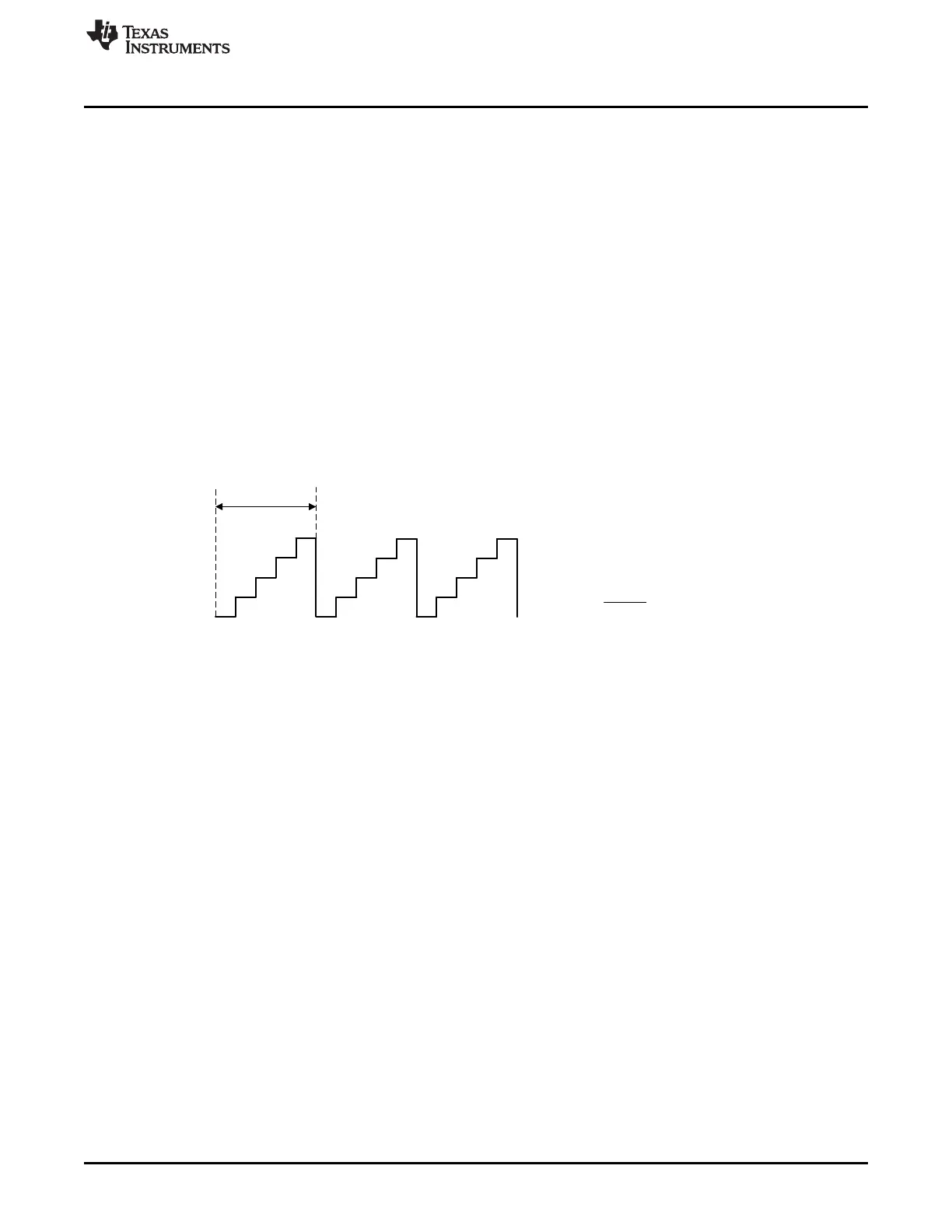
Figure 5-11. Time-Base Frequency and Period Calculation
 Loading...