28x
I2C
I2C
EPROM
I2C
I2C
28x
V
DD
Pullup
resistors
Serial data (SDA)
Serial clock (SCL)
controller
www.ti.com
Introduction
617
SPRUI07–March 2020
Submit Documentation Feedback
Copyright © 2020, Texas Instruments Incorporated
Inter-Integrated Circuit Module (I2C)
11.1 Introduction
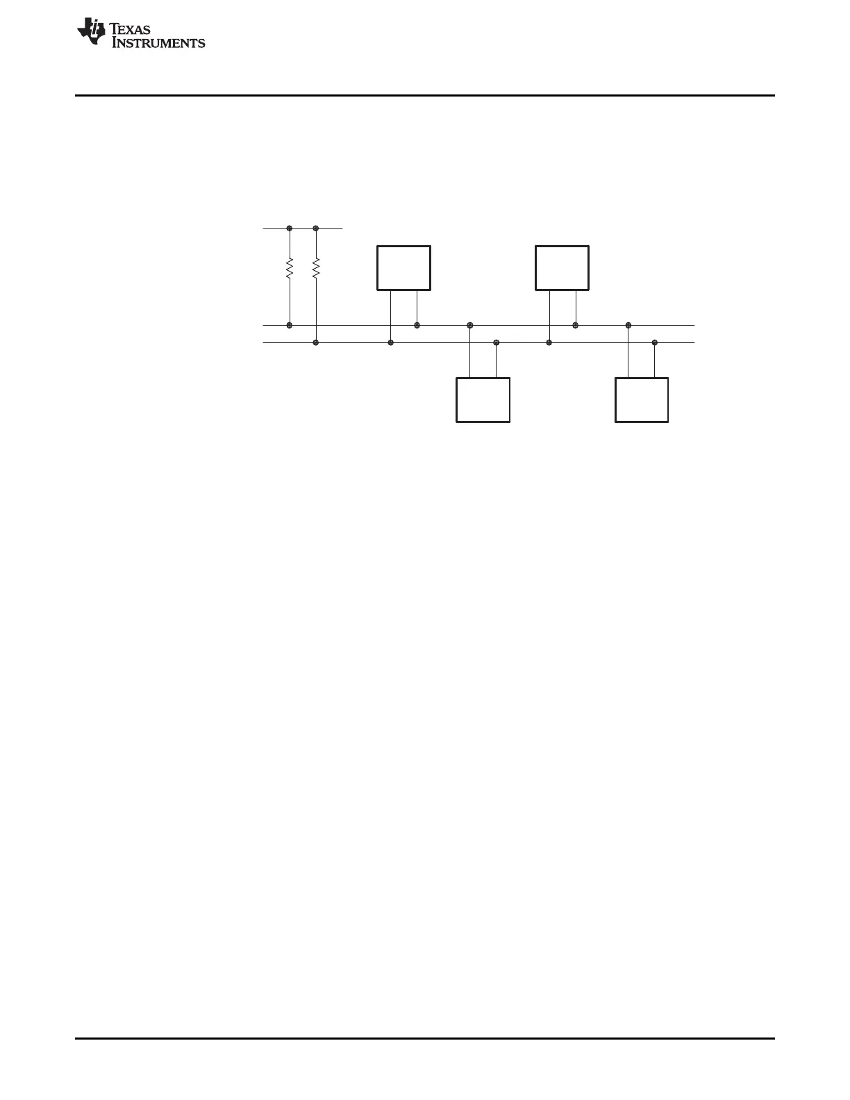
The I2C module supports any slave or master I2C-compatible device. Figure 11-1 shows an example of
multiple I2C modules connected for a two-way transfer from one device to other devices.
Figure 11-1. Multiple I2C Modules Connected
11.1.1 Features
The I2C module has the following features:
• Compliance with the NXP Semiconductors I2C bus specification (version 2.1):
– Support for 8-bit format transfers
– 7-bit and 10-bit addressing modes
– General call
– START byte mode
– Support for multiple master-transmitters and slave-receivers
– Support for multiple slave-transmitters and master-receivers
– Combined master transmit/receive and receive/transmit mode
– Data transfer rate from 10 kbps up to 400 kbps (Fast-mode)
• Receive FIFO and Transmitter FIFO (16-deep x 8-bit FIFO)
• Supports two ePIE interrupts:
– I2Cx Interrupt – Any of the below events can be configured to generate an I2Cx interrupt:
• Transmit-data ready
• Receive-data ready
• Register-access ready
• No-acknowledgment received
• Arbitration lost
• Stop condition detected
• Addressed as slave
– I2Cx_FIFO interrupts:
• Transmit FIFO interrupt
• Receive FIFO interrupt
• Module enable/disable capability
• Free data format mode
 Loading...