Empty
Data 2 Data 3 Data 4
Empty
Data 1 Data 2 Data 3
Empty
Data 1 Data 2 Data 3
Empty
Data 1 Data 2 Data 3
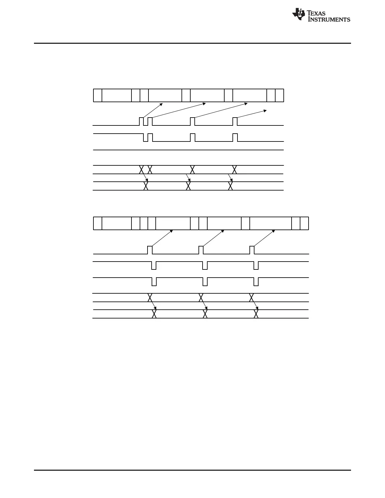
S
Slave
Address
R A Data 1 A Data 2 A Data 2 nA P
S
Slave
Address
R A Data 1 A Data 2 A Data 3 nA P
Left in I2CDXR
Interrupt
XRDY
XSMT
I2CDXR
I2CXSR
b) BC = 0
Interrupt
XRDY
XSMT
I2CDXR
I2CXSR
b) BC = 1
Slave-Transmitter
Interrupt Requests Generated by the I2C Module
www.ti.com
630
SPRUI07–March 2020
Submit Documentation Feedback
Copyright © 2020, Texas Instruments Incorporated
Inter-Integrated Circuit Module (I2C)
Figure 11-16. Backwards Compatibility Mode Bit, Slave Transmitter
11.4.2 I2C FIFO Interrupts
In addition to the seven basic I2C interrupts, the transmit and receive FIFOs each contain the ability to
generate an interrupt (I2CINT2A). The transmit FIFO can be configured to generate an interrupt after
transmitting a defined number of bytes, up to 16. The receive FIFO can be configured to generate an
interrupt after receiving a defined number of bytes, up to 16. These two interrupt sources are ORed
together into a single maskable CPU interrupt. Figure 11-17 shows the structure of I2C FIFO interrupt.
The interrupt service routine can then read the FIFO interrupt status flags to determine from which source
the interrupt came. See the I2C transmit FIFO register (I2CFFTX) and the I2C receive FIFO register
(I2CFFRX) descriptions.
 Loading...