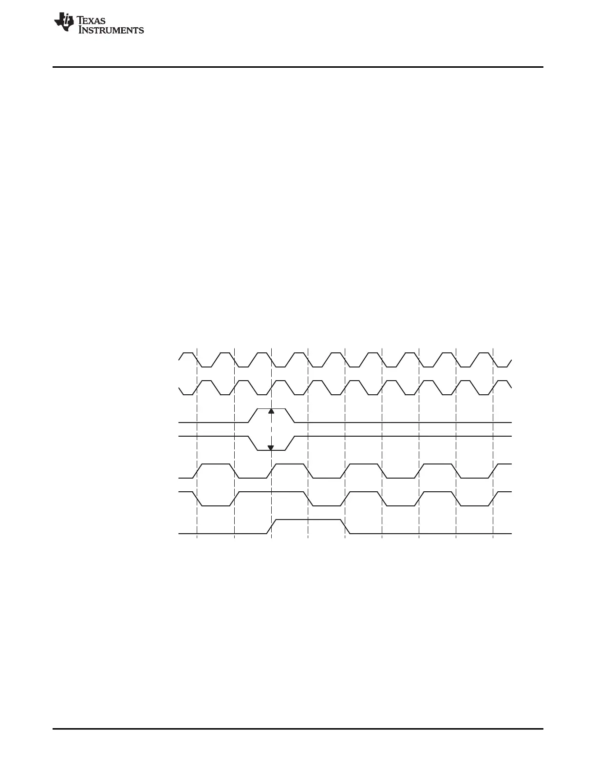
FSG
(Needs resynchronization)
CLKG
resynchronize)
(No need to
CLKG
(FSRP=1)
FSR external
(FSRP=0)
FSR external
CLKR
CLKR
www.ti.com
McBSP Sample Rate Generator
675
SPRUI07–March 2020
Submit Documentation Feedback
Copyright © 2020, Texas Instruments Incorporated
Multichannel Buffered Serial Port (McBSP)
by the arrival of the next frame-synchronization pulse on the FSR pin.
If GSYNC = 0, CLKG runs freely and is not resynchronized, and the frame-synchronization period on FSG
is determined by FPER.
12.4.3.1 Operating the Transmitter Synchronously with the Receiver
When GSYNC = 1, the transmitter can operate synchronously with the receiver, provided that:
• FSX is programmed to be driven by FSG (FSGM = 1 in SRGR2 and FSXM = 1 in PCR). If the input
FSR has appropriate timing so that it can be sampled by the falling edge of CLKG, it can be used,
instead, by setting FSXM = 0 and connecting FSR to FSX externally.
• The sample rate generator clock drives the transmit and receive clocking (CLKRM = CLKXM = 1 in
PCR).
12.4.3.2 Synchronization Examples
Figure 12-19 and Figure 12-20 show the clock and frame-synchronization operation with various polarities
of CLKR and FSR. These figures assume FWID = 0 in SRGR1, for an FSG pulse that is one CLKG cycle
wide. The FPER bits of SRGR2 are not programmed; the period from the start of a frame-synchronization
pulse to the start of the next pulse is determined by the arrival of the next inactive-to-active transition on
the FSR pin. Each of the figures shows what happens to CLKG when it is initially synchronized and
GSYNC = 1, and when it is not initially synchronized and GSYNC = 1. Figure 12-20 has a slower CLKG
frequency (it has a larger divide-down value in the CLKGDV bits of SRGR1).
Figure 12-19. CLKG Synchronization and FSG Generation When GSYNC = 1 and CLKGDV = 1
 Loading...