INT1
to
INT12
INT14
28x
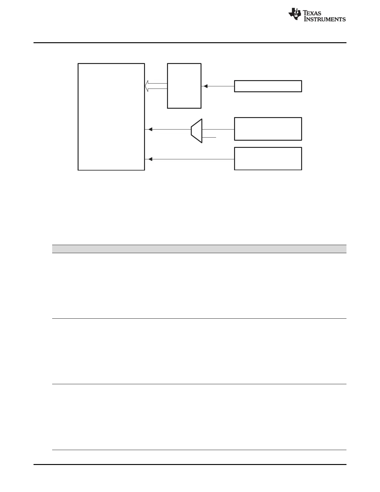
CPU
TINT2
TINT0
PIE
CPU-TIMER0
CPU-TIMER2
(ReservedforDSP/BIOS)
INT13
TINT1
CPU-TIMER1
XINT13
Clocking and System Control
www.ti.com
82
SPRUI07–March 2020
Submit Documentation Feedback
Copyright © 2020, Texas Instruments Incorporated
System Control and Interrupts
Figure 1-32. CPU-Timer Interrupt Signals and Output Signal
A The timer registers are connected to the Memory Bus of the 28x processor.
B The timing of the timers is synchronized to SYSCLKOUT of the processor clock.
The general operation of the CPU timer is as follows: The 32-bit counter register TIMH:TIM is loaded with
the value in the period register PRDH:PRD. The counter decrements once every (TPR[TDDRH:TDDR]+1)
SYSCLKOUT cycles where TDDRH:TDDR is the timer divider. When the counter reaches 0, a timer
interrupt output signal generates an interrupt pulse. The registers listed in Table 1-31 are used to
configure the timers.
Table 1-31. CPU Timers 0, 1, 2 Configuration and Control Registers
Name Address Size (x16) Description Bit Description
TIMER0TIM 0x0C00 1 CPU-Timer 0, Counter Register Figure 1-33
TIMER0TIMH 0x0C01 1 CPU-Timer 0, Counter Register High Figure 1-34
TIMER0PRD 0x0C02 1 CPU-Timer 0, Period Register Figure 1-35
TIMER0PRDH 0x0C03 1 CPU-Timer 0, Period Register High Figure 1-36
TIMER0TCR 0x0C04 1 CPU-Timer 0, Control Register Figure 1-37
Reserved 0x0C05 1
TIMER0TPR 0x0C06 1 CPU-Timer 0, Prescale Register Figure 1-38
TIMER0TPRH 0x0C07 1 CPU-Timer 0, Prescale Register High Figure 1-39
TIMER1TIM 0x0C08 1 CPU-Timer 1, Counter Register Figure 1-33
TIMER1TIMH 0x0C09 1 CPU-Timer 1, Counter Register High Figure 1-34
TIMER1PRD 0x0C0A 1 CPU-Timer 1, Period Register Figure 1-35
TIMER1PRDH 0x0C0B 1 CPU-Timer 1, Period Register High Figure 1-36
TIMER1TCR 0x0C0C 1 CPU-Timer 1, Control Register Figure 1-37
Reserved 0x0C0D 1
TIMER1TPR 0x0C0E 1 CPU-Timer 1, Prescale Register Figure 1-38
TIMER1TPRH 0x0C0F 1 CPU-Timer 1, Prescale Register High Figure 1-39
TIMER2TIM 0x0C10 1 CPU-Timer 2, Counter Register Figure 1-33
TIMER2TIMH 0x0C11 1 CPU-Timer 2, Counter Register High Figure 1-34
TIMER2PRD 0x0C12 1 CPU-Timer 2, Period Register Figure 1-35
TIMER2PRDH 0x0C13 1 CPU-Timer 2, Period Register High Figure 1-36
TIMER2TCR 0x0C14 1 CPU-Timer 2, Control Register Figure 1-37
Reserved 0x0C15 1
TIMER2TPR 0x0C16 1 CPU-Timer 2, Prescale Register Figure 1-38
TIMER2TPRH 0x0C17 1 CPU-Timer 2, Prescale Register High Figure 1-39
 Loading...