www.ti.com
Peripheral Interrupt Expansion (PIE)
159
SPRUI07–March 2020
Submit Documentation Feedback
Copyright © 2020, Texas Instruments Incorporated
System Control and Interrupts
1.6.4.6 Interrupt Enable Register (IER) — CPU Register
The IER is a 16-bit CPU register. The IER contains enable bits for all the maskable CPU interrupt levels
(INT1-INT14, RTOSINT and DLOGINT). Neither NMI nor XRS is included in the IER; thus, IER has no
effect on these interrupts.
You can read the IER to identify enabled or disabled interrupt levels, and you can write to the IER to
enable or disable interrupt levels. To enable an interrupt level, set its corresponding IER bit to one using
the OR IER instruction. To disable an interrupt level, set its corresponding IER bit to zero using the AND
IER instruction. When an interrupt is disabled, it is not acknowledged, regardless of the value of the INTM
bit. When an interrupt is enabled, it is acknowledged if the corresponding IFR bit is one and the INTM bit
is zero.
When using the OR IER and AND IER instructions to modify IER bits make sure they do not modify the
state of bit 15 (RTOSINT) unless a real-time operating system is present.
When a hardware interrupt is serviced or an INTR instruction is executed, the corresponding IER bit is
cleared automatically. When an interrupt is requested by the TRAP instruction the IER bit is not cleared
automatically. In the case of the TRAP instruction if the bit needs to be cleared it must be done by the
interrupt service routine.
At reset, all the IER bits are cleared to 0, disabling all maskable CPU level interrupts.
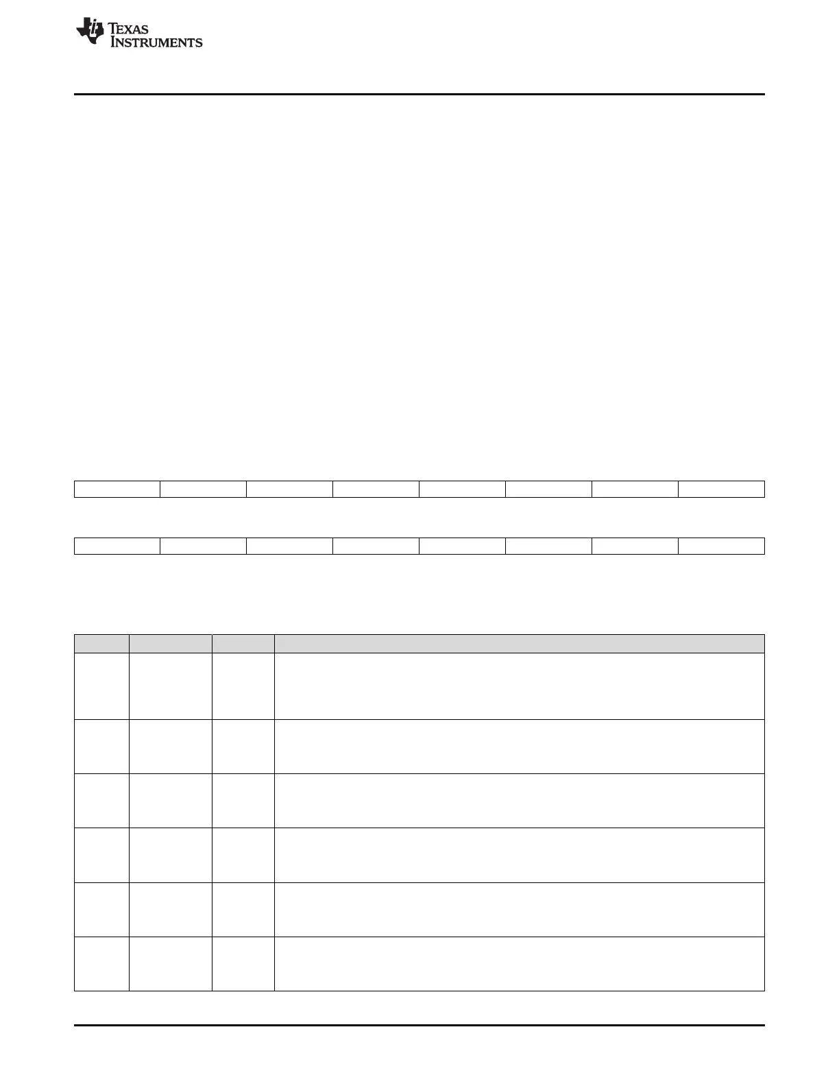
The IER register is shown in Figure 1-89, and descriptions of the bits follow the figure.
Figure 1-89. Interrupt Enable Register (IER) — CPU Register
15 14 13 12 11 10 9 8
RTOSINT DLOGINT INT14 INT13 INT12 INT11 INT10 INT9
R/W-0 R/W-0 R/W-0 R/W-0 R/W-0 R/W-0 R/W-0 R/W-0
7 6 5 4 3 2 1 0
INT8 INT7 INT6 INT5 INT4 INT3 INT2 INT1
R/W-0 R/W-0 R/W-0 R/W-0 R/W-0 R/W-0 R/W-0 R/W-0
LEGEND: R/W = Read/Write; R = Read only; -n = value after reset
Table 1-119. Interrupt Enable Register (IER) — CPU Register Field Descriptions
Bits Field Value Description
15 RTOSINT Real-time operating system interrupt enable. RTOSINT enables or disables the CPU RTOS
interrupt.
0 Real-time operating system interrupt is disabled
1 Real-time operating system interrupt is enabled
14 DLOGINT Data logging interrupt enable. DLOGINT enables or disables the CPU data logging interrupt.
0 Data logging interrupt is disabled
1 Data logging interrupt is enabled
13 INT14 Interrupt 14 enable. INT14 enables or disables CPU interrupt level INT14.
0 Level INT14 is disabled
1 Level INT14 is enabled
12 INT13 Interrupt 13 enable. INT13 enables or disables CPU interrupt level INT13.
0 Level INT13 is disabled
1 Level INT13 is enabled
11 INT12 Interrupt 12 enable. INT12 enables or disables CPU interrupt level INT12.
0 Level INT12 is disabled
1 Level INT12 is enabled
10 INT11 Interrupt 11 enable. INT11 enables or disables CPU interrupt level INT11.
0 Level INT11 is disabled
1 Level INT11 is enabled
 Loading...