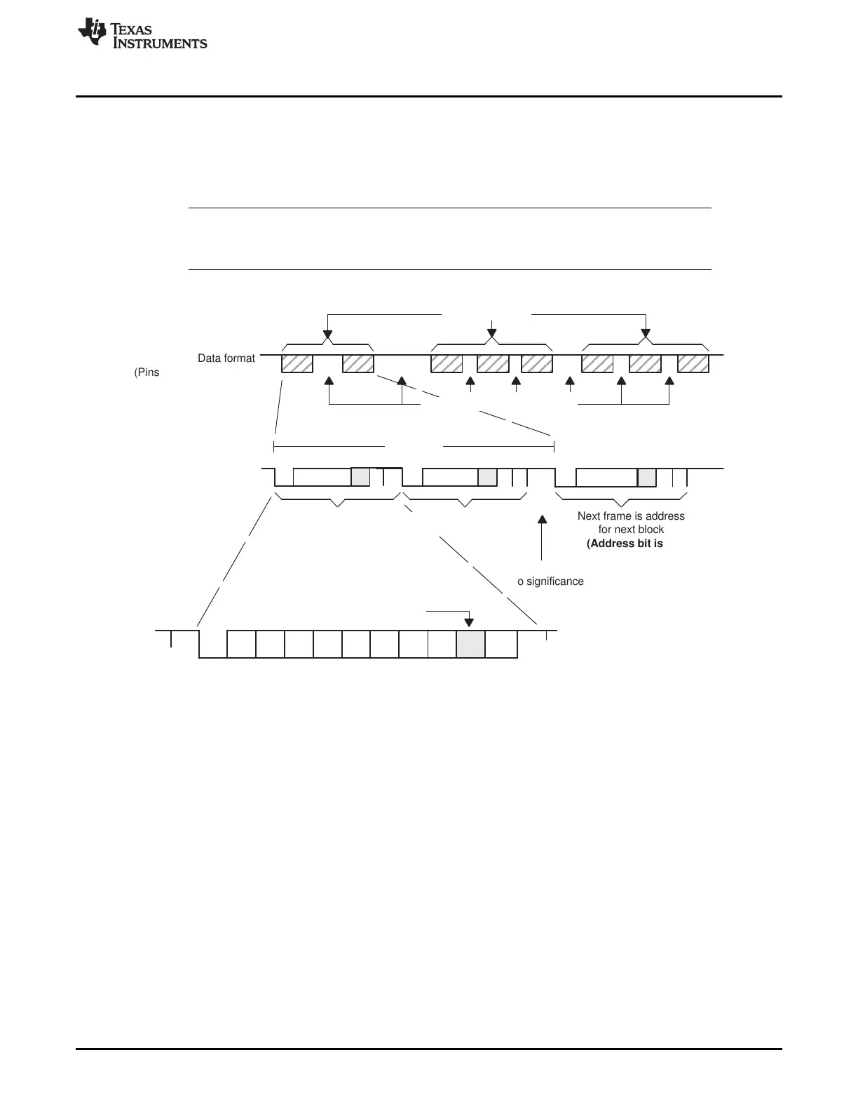
Data format
(Pins SCIRXD, SCITXD)
Data format expanded
First frame within
block is address
(Address bit is 1)
1
Idle time is of
no significance
Next frame is address
for next block
(Address bit is 1)
Start LSB
Stop
Address-bit mode frame example
Address bit
Frame within block
(Address bit is 0)
1
Start
Start
Start
One block
Idle periods of no significance
Blocks of frames
www.ti.com
SCI Communication Format
589
SPRUI07–March 2020
Submit Documentation Feedback
Copyright © 2020, Texas Instruments Incorporated
Serial Communications Interface (SCI)
When this address value is transferred to the TXSHF register and shifted out, its address bit is sent as
a 1. This flags the other processors on the serial link to read the address.
2. Write to SCITXBUF and TXWAKE after TXSHF and WUT are loaded. (Can be written to immediately
since both TXSHF and WUT are both double-buffered.
3. Leave the TXWAKE bit set to 0 to transmit non-address frames in the block.
NOTE: As a general rule, the address-bit format is typically used for data frames of 11 bytes or less.
This format adds one bit value (1 for an address frame, 0 for a data frame) to all data bytes
transmitted. The idle-line format is typically used for data frames of 12 bytes or more.
Figure 10-6. Address-Bit Multiprocessor Communication Format
10.10 SCI Communication Format
The SCI asynchronous communication format uses either single line (one way) or two line (two way)
communications. In this mode, the frame consists of a start bit, one to eight data bits, an optional
even/odd parity bit, and one or two stop bits (shown in Figure 10-7). There are eight SCICLK periods per
data bit.
The receiver begins operation on receipt of a valid start bit. A valid start bit is identified by four
consecutive internal SCICLK periods of zero bits as shown in Figure 10-7. If any bit is not zero, then the
processor starts over and begins looking for another start bit.
For the bits following the start bit, the processor determines the bit value by making three samples in the
middle of the bits. These samples occur on the fourth, fifth, and sixth SCICLK periods, and bit-value
determination is on a majority (two out of three) basis. Figure 10-7 illustrates the asynchronous
communication format for this with a start bit showing where a majority vote is taken.
Since the receiver synchronizes itself to frames, the external transmitting and receiving devices do not
have to use a synchronized serial clock. The clock can be generated locally.
 Loading...