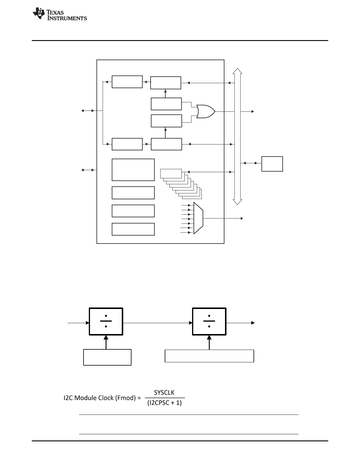
I2CPSC + 1
SYSCLK
I2C Module Clock
(ICCL + d) + (ICCH + d)
Master Clock on SCL pin
I2CXSR I2CDXR
I2CRSR I2CDRR
Clock
synchronizer
Prescaler
Noise filters
Arbitrator
I2C INT
Peripheral bus
Interrupt to
CPU/PIE
SDA
SCL
Control/status
registers
CPU
I2C module
TX FIFO
RX FIFO
FIFO Interrupt
to CPU/PIE
www.ti.com
Introduction
619
SPRUI07–March 2020
Submit Documentation Feedback
Copyright © 2020, Texas Instruments Incorporated
Inter-Integrated Circuit Module (I2C)
Figure 11-2. I2C Module Conceptual Block Diagram
11.1.4 Clock Generation
The I2C module clock determines the frequency at which the I2C module operates. A programmable
prescaler in the I2C module divides down the SYSCLK to produce the I2C module clock and this I2C
module clock is divided further to produce the I2C master clock on the SCL pin. Figure 11-3 shows the
clock generation diagram for I2C module.
Figure 11-3. Clocking Diagram for the I2C Module
To specify the divide-down value, initialize the IPSC field of the prescaler register, I2CPSC. The resulting
frequency is:
NOTE: To meet all of the I2C protocol timing specifications, the I2C module clock must be between
7 - 12 MHz.
 Loading...