0-15112-12796-11180-9564-7948-6332-4716-310-15
Block
Channels
FS(R/X)
ÁÁÁÁÁÁÁÁÁÁÁÁÁÁÁÁÁÁÁÁÁÁÁÁÁ
ÁÁÁÁÁÁÁÁÁÁÁÁÁÁÁÁÁÁÁÁÁÁÁÁÁ
ÁÁÁÁÁÁÁÁÁÁÁÁÁÁÁÁÁÁÁÁÁÁÁÁÁ
ÁÁÁÁÁÁÁÁÁÁÁÁÁÁÁÁÁÁÁÁÁÁÁÁÁ
0 1 2 3 4 5 6 7 0
Partition A B C D E F G H A
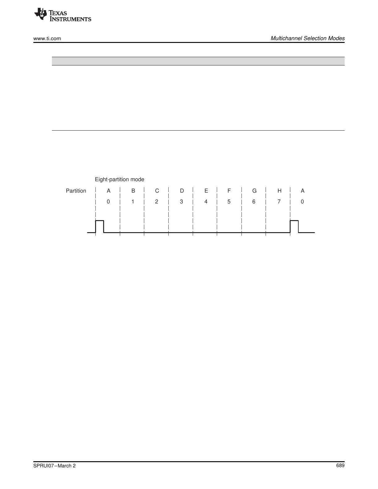
Eight-partition mode
www.ti.com
Multichannel Selection Modes
689
SPRUI07–March 2020
Submit Documentation Feedback
Copyright © 2020, Texas Instruments Incorporated
Multichannel Buffered Serial Port (McBSP)
Table 12-12. Transmit Channel Assignment and Control When Eight Transmit Partitions Are Used
Transmit Partition Assigned Block of Transmit Channels Register Used For Channel Control
A Block 0: channels 0 through 15 XCERA
B Block 1: channels 16 through 31 XCERB
C Block 2: channels 32 through 47 XCERC
D Block 3: channels 48 through 63 XCERD
E Block 4: channels 64 through 79 XCERE
F Block 5: channels 80 through 95 XCERF
G Block 6: channels 96 through 111 XCERG
H Block 7: channels 112 through 127 XCERH
Figure 12-34 shows an example of the McBSP using the 8-partition mode. In response to a frame-
synchronization pulse, the McBSP begins a frame transfer with partition A and then activates B, C, D, E,
F, G, and H to complete a 128-word frame.
Figure 12-34. McBSP Data Transfer in the 8-Partition Mode
12.6.6 Receive Multichannel Selection Mode
The RMCM bit of MCR1 determines whether all channels or only selected channels are enabled for
reception. When RMCM = 0, all 128 receive channels are enabled and cannot be disabled. When RMCM
= 1, the receive multichannel selection mode is enabled. In this mode:
• Channels can be individually enabled or disabled. The only channels enabled are those selected in the
appropriate receive channel enable registers (RCERs). The way channels are assigned to the RCERs
depends on the number of receive channel partitions (2 or 8), as defined by the RMCME bit of MCR1.
• If a receive channel is disabled, any bits received in that channel are passed only as far as the receive
buffer register(s) (RBR(s)). The receiver does not copy the content of the RBR(s) to the DRR(s), and
as a result, does not set the receiver ready bit (RRDY). Therefore, no DMA synchronization event
(REVT) is generated and, if the receiver interrupt mode depends on RRDY (RINTM = 00b), no interrupt
is generated.
As an example of how the McBSP behaves in the receive multichannel selection mode, suppose you
enable only channels 0, 15, and 39 and that the frame length is 40. The McBSP:
1. Accepts bits shifted in from the DR pin in channel 0
2. Ignores bits received in channels 1-14
3. Accepts bits shifted in from the DR pin in channel 15
4. Ignores bits received in channels 16-38
5. Accepts bits shifted in from the DR pin in channel 39
12.6.7 Transmit Multichannel Selection Modes
The XMCM bits of XCR2 determine whether all channels or only selected channels are enabled and
unmasked for transmission. More details on enabling and masking are in Section 12.6.7.1. The McBSP
has three transmit multichannel selection modes (XMCM = 01b, XMCM = 10b, and XMCM = 11b), which
are described in the following table.
 Loading...