ADC Registers
www.ti.com
480
SPRUI07–March 2020
Submit Documentation Feedback
Copyright © 2020, Texas Instruments Incorporated
Analog-to-Digital Converter (ADC)
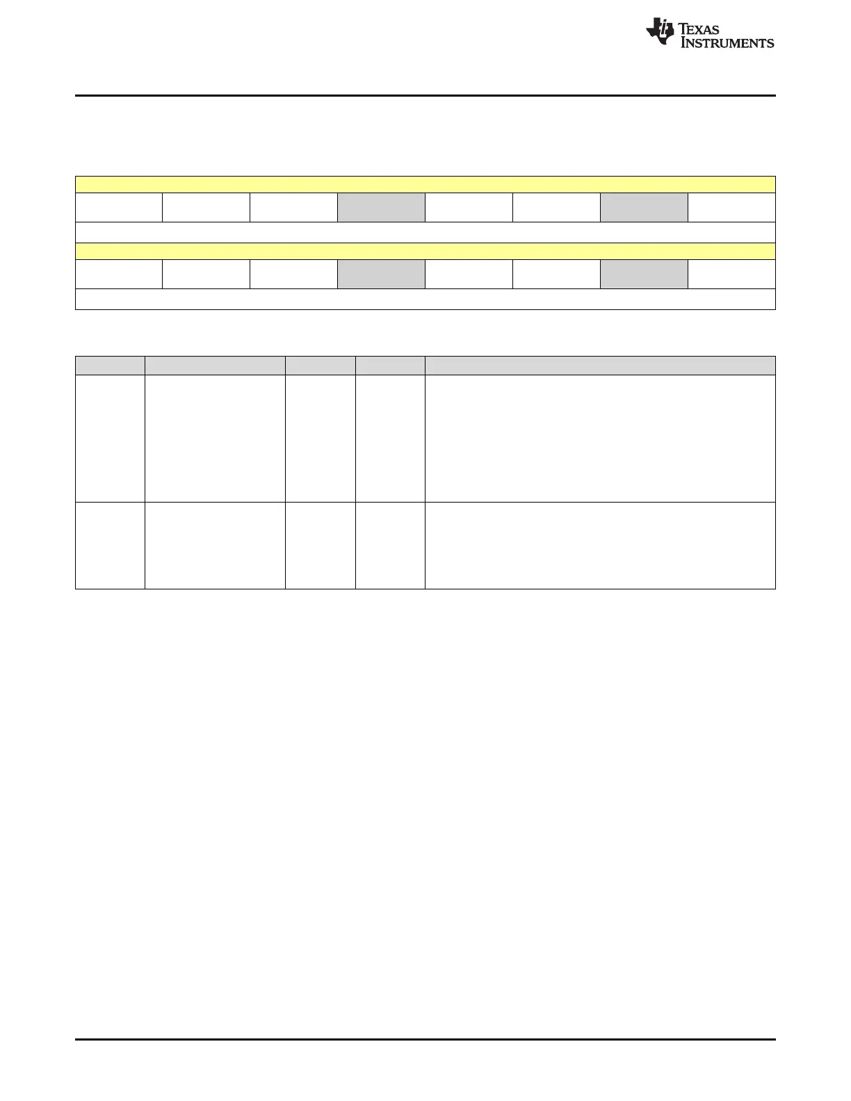
7.4.2 ADCTRL2 Register (Offset = 1h) [reset = 0h]
ADCTRL2 is shown in Figure 7-16 and described in Table 7-11.
Figure 7-16. ADCTRL2 Register
15 14 13 12 11 10 9 8
ePWM_SOCB_
SEQ
RST_SEQ1 SOC_SEQ1 RESERVED INT_ENA_SEQ
1
INT_MOD_SE
Q1
RESERVED ePWM_SOCA_
SEQ1
R/W-0h R/W-0h R/W-0h R-0h R/W-0h R/W-0h R-0h R/W-0h
7 6 5 4 3 2 1 0
EXT_SOC_SE
Q1
RST_SEQ2 SOC_SEQ2 RESERVED INT_ENA_SEQ
2
INT_MOD_SE
Q2
RESERVED ePWM_SOCB_
SEQ2
R/W-0h R/W-0h R/W-0h R-0h R/W-0h R/W-0h R-0h R/W-0h
Table 7-11. ADCTRL2 Register Field Descriptions
Bit Field Type Reset Description
15 ePWM_SOCB_SEQ R/W 0h
ePWM SOCB enable for cascaded sequencer (Note: This bit is
active only in cascaded mode.)
0h = No action
1h = Setting this bit allows the cascaded sequencer to be started by
an ePWM SOCB signal. The ePWM modules can be programmed to
start a conversion on various events. See the TMS320x28xx , 28xxx
Enhanced Pulse Width Modulation Module Reference Guide
(literature number SPRU791) for more information on the ePWM
modules.
14 RST_SEQ1 R/W 0h Reset sequencer1 Writing a 1 to this bit resets SEQ1 or the
cascaded sequencer immediately to an initial "pretriggered" state,
i.e., waiting for a trigger at CONV00. A currently active conversion
sequence will be aborted.
0h = No action
1h = Immediately reset sequencer to state CONV00
 Loading...