None
SEQ1INT
SEQ2INT
EPWM5SOCB
EPWM6SOCA
EPWM6SOCB
.
.
.
MODE.CHx
[PERINTSEL]
CONTROL.CHx
[PERINTFRC]
CONTROL.CHx
[PERINTCLR]
Clear
Set
Latch
Clearperipheralinterrupt
triggerflagifappropriate
CONTROL.CHx[PERINTFLG]
Peripheral
Int
MODE.CHx
[PERINTE]
Clearinterrupt
DMA
channelx
processing
logic
Architecture
www.ti.com
498
SPRUI07–March 2020
Submit Documentation Feedback
Copyright © 2020, Texas Instruments Incorporated
Direct Memory Access (DMA) Module
8.2.2 Peripheral Interrupt Event Trigger Sources
The peripheral interrupt event trigger can be independently configured as one of eighteen different
sources for each of the six DMA channels. Included in these sources are 8 external interrupt signals which
can be connected to most of the general-purpose input/output (GPIO) pins on the device. This adds
significant flexibility to the event trigger capabilities. A bit field called PERINTSEL in the MODE register of
each channel is used to select that channels interrupt trigger source. An active peripheral interrupt trigger
will be latched into the PERINTFLG bit of the CONTROL register, and if the respective interrupt and DMA
channel is enabled (see the MODE.CHx[PERINTE] and CONTROL.CHx[RUNSTS] bits), it will be serviced
by the DMA channel. Upon receipt of a peripheral interrupt event signal, the DMA will automatically send a
clear signal to the interrupt source so that subsequent interrupt events will occur.
Regardless of the value of the MODE.CHx[PERINTSEL] bit field, software can always force a trigger by
using the CONTROL.CHx[PERINTFRC] bit. Likewise, software can always clear a pending DMA trigger
using the CONTROL.CHx[PERINTCLR] bit.
Once a particular interrupt trigger sets a channel’s PERINTFLG bit, the bit stays pending until the priority
logic of the state machine starts the burst transfer for that channel. Once the burst transfer starts, the flag
is cleared. If a new interrupt trigger is generated while a burst is in progress, the burst will complete before
responding to the new interrupt trigger (after proper prioritization). If a third interrupt trigger occurs before
the pending interrupt is serviced, an error flag is set in the CONTROL.CHx[OVRFLG] bit. If a peripheral
interrupt trigger occurs at the same time as the latched flag is being cleared, the peripheral interrupt
trigger has priority and the PERINTFLG will remain set.
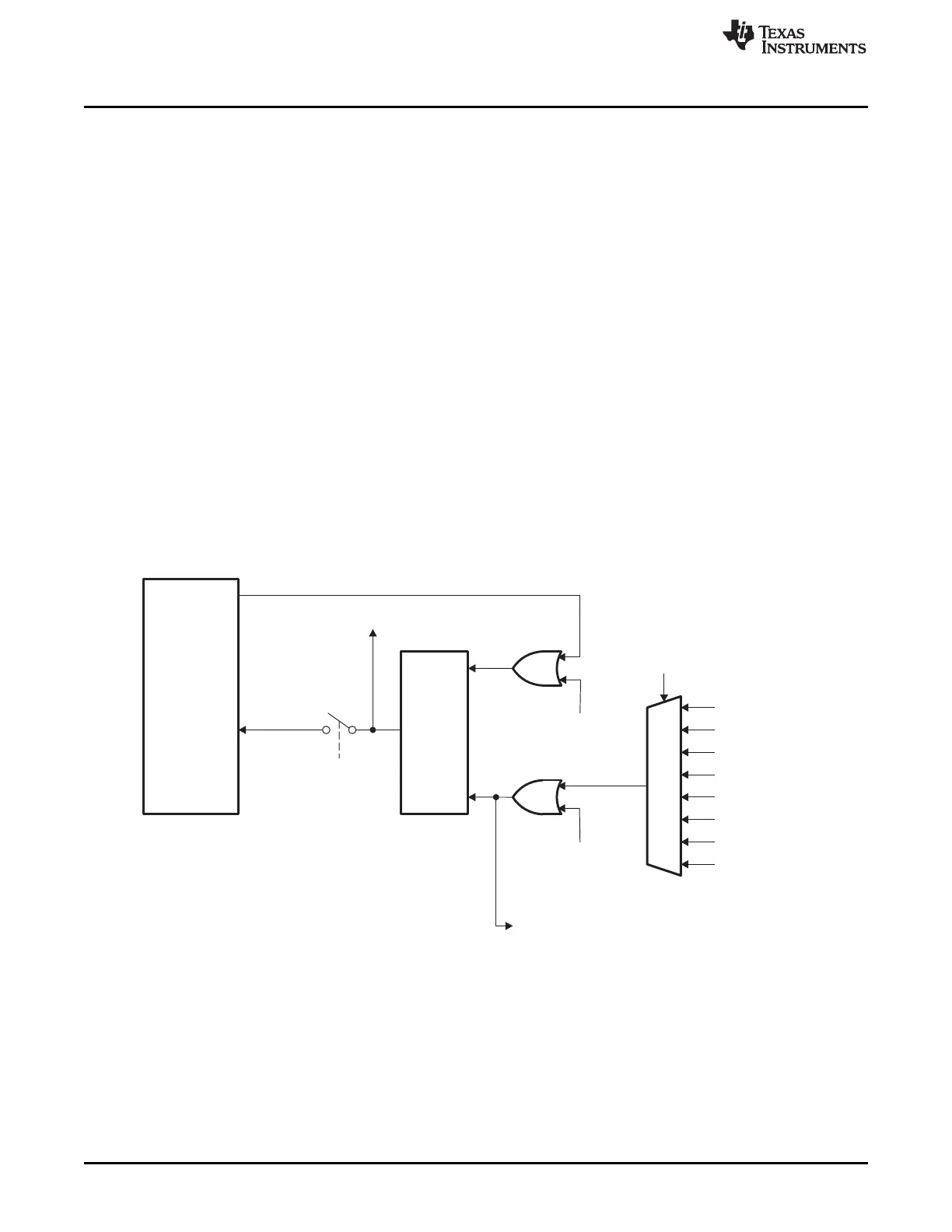
Figure 8-2 shows a diagram of the trigger select circuit. See the MODE.CHx[PERINTSEL] bit field
description for the complete list of peripheral interrupt trigger sources.
Figure 8-2. Peripheral Interrupt Trigger Input Diagram
 Loading...