000
2-0
Value
15-3
A-law format in DXR1
µ-law format in DXR1
00Value
1-015-2
www.ti.com
Transmitter Configuration
729
SPRUI07–March 2020
Submit Documentation Feedback
Copyright © 2020, Texas Instruments Incorporated
Multichannel Buffered Serial Port (McBSP)
12.9.12.2 Format for Data To Be Compressed
For transmission using μ-law compression, make sure the 14 data bits are left-justified in DXR1, with the
remaining two low-order bits filled with 0s as shown in Figure 12-54.
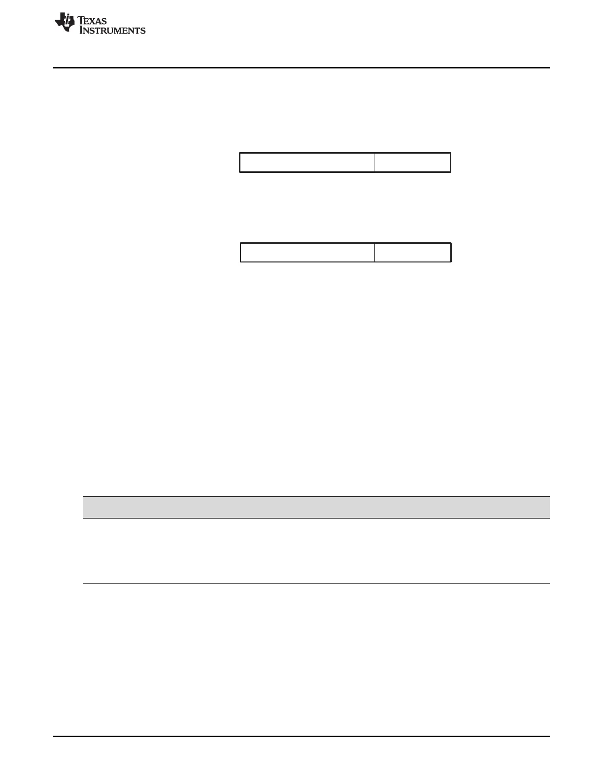
Figure 12-54. μ-Law Transmit Data Companding Format
For transmission using A-law compression, make sure the 13 data bits are left-justified in DXR1, with the
remaining three low-order bits filled with 0s as shown in Figure 12-55.
Figure 12-55. A-Law Transmit Data Companding Format
12.9.12.3 Capability to Compand Internal Data
If the McBSP is otherwise unused (the serial port transmit and receive sections are reset), the
companding hardware can compand internal data. See Section 12.3.2.2, Capability to Compand Internal
Data.
12.9.12.4 Option to Transmit LSB First
Normally, the McBSP transmit or receives all data with the most significant bit (MSB) first. However,
certain 8-bit data protocols (that do not use companded data) require the least significant bit (LSB) to be
transferred first. If you set XCOMPAND = 01b in XCR2, the bit ordering of 8-bit words is reversed (LSB
first) before being sent from the serial port. Similar to companding, this feature is enabled only if the
appropriate word length bits are set to 0, indicating that 8-bit words are to be transferred serially. If either
phase of the frame does not have an 8-bit word length, the McBSP assumes the word length is eight bits
and LSB-first ordering is done.
12.9.13 Transmit Data Delay
Table 12-60. Register Bits Used to Set the Transmit Data Delay
Register Bit Name Function Type
Reset
Value
XCR2 1-0 XDATDLY Transmitter data delay R/W 00
XDATDLY = 00 0-bit data delay
XDATDLY = 01 1-bit data delay
XDATDLY = 10 2-bit data delay
XDATDLY = 11 Reserved
12.9.13.1 Data Delay
The start of a frame is defined by the first clock cycle in which frame synchronization is found to be active.
The beginning of actual data reception or transmission with respect to the start of the frame can be
delayed if necessary. This delay is called data delay.
XDATDLY specifies the data delay for transmission. The range of programmable data delay is zero to two
bit-clocks (XDATDLY = 00b-10b), as described in Table 12-60 and Figure 12-56. In this figure, the data
transferred is an 8-bit value with bits labeled B7, B6, B5, and so on. Typically a 1-bit delay is selected,
because data often follows a 1-cycle active frame-synchronization pulse.
 Loading...