www.ti.com
McBSP Registers
751
SPRUI07–March 2020
Submit Documentation Feedback
Copyright © 2020, Texas Instruments Incorporated
Multichannel Buffered Serial Port (McBSP)
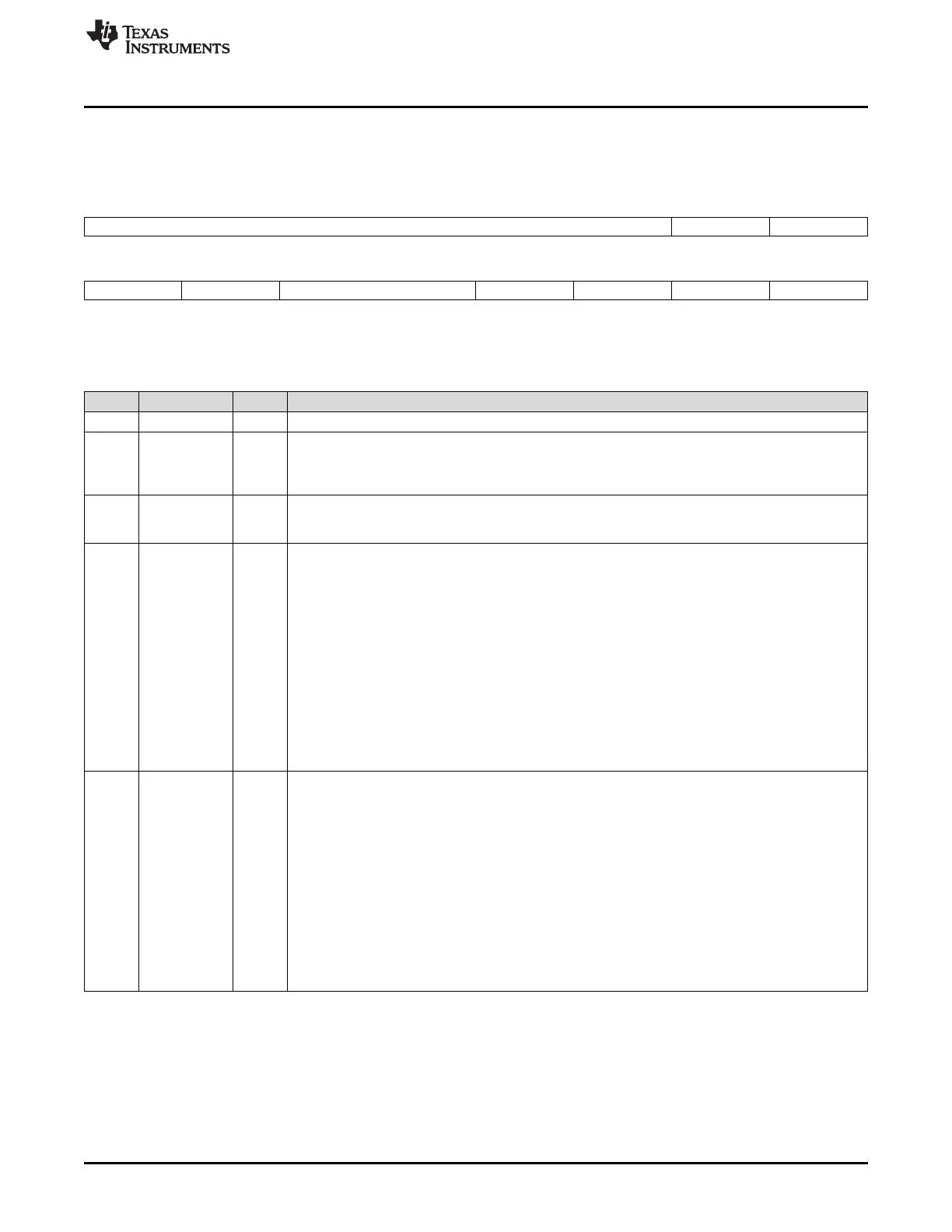
12.15.4.2 Serial Port Control 2 Register (SPCR2)
The serial port control 2 register (SPCR2) is shown in Figure 12-70 and described in Table 12-78.
Figure 12-70. Serial Port Control 2 Register (SPCR2)
15 10 9 8
Reserved FREE SOFT
R-0 R/W-0 R/W-0
7 6 5 4 3 2 1 0
FRST GRST XINTM XSYNCERR XEMPTY XRDY XRST
R/W-0 R/W-0 R/W-0 R/W-0 R-0 R-0 R/W-0
LEGEND: R/W = Read/Write; R = Read only; -n = value after reset
Table 12-78. Serial Port Control 2 Register (SPCR2) Field Descriptions
Bit Field Value Description
15-10 Reserved 0 Reserved bits (not available for your use). They are read-only bits and return 0s when read.
9 FREE Free run bit. When a breakpoint is encountered in the high-level language debugger, FREE determines
whether the McBSP transmit and receive clocks continue to run or whether they are affected as
determined by the SOFT bit. When one of the clocks stops, the corresponding data transfer
(transmission or reception) stops.
8 SOFT Soft stop bit. When FREE = 0, SOFT determines the response of the McBSP transmit and receive
clocks when a breakpoint is encountered in the high-level language debugger. When one of the clocks
stops, the corresponding data transfer (transmission or reception) stops.
7 FRST Frame-synchronization logic reset bit. The sample rate generator of the McBSP includes frame-
synchronization logic to generate an internal frame-synchronization signal. You can use FRST to take
the frame-synchronization logic into and out of its reset state. This bit has a negative polarity; FRST =
0 indicates the reset state.
0 If you read a 0, the frame-synchronization logic is in its reset state.
If you write a 0, you reset the frame-synchronization logic.
In the reset state, the frame-synchronization logic does not generate a frame-synchronization signal
(FSG).
1 If you read a 1, the frame-synchronization logic is enabled.
If you write a 1, you enable the frame-synchronization logic by taking it out of its reset state.
When the frame-synchronization logic is enabled (FRST = 1) and the sample rate generator as a
whole is enabled (GRST = 1), the frame-synchronization logic generates the frame-synchronization
signal FSG as programmed.
6 GRST Sample rate generator reset bit. You can use GRST to take the McBSP sample rate generator into and
out of its reset state. This bit has a negative polarity; GRST = 0 indicates the reset state.
To read about the effects of a sample rate generator reset, see Section 12.10.2.
0 If you read a 0, the sample rate generator is in its reset state.
If you write a 0, you reset the sample rate generator.
If GRST = 0 due to a reset, CLKG is driven by the CPU clock divided by 2, and FSG is driven low
(inactive). If GRST = 0 due to program code, CLKG and FSG are both driven low (inactive).
1 If you read a 1, the sample rate generator is enabled.
If you write a 1, you enable the sample rate generator by taking it out of its reset state.
When enabled, the sample rate generator generates the clock signal CLKG as programmed in the
sample rate generator registers. If FRST = 1, the generator also generates the frame-synchronization
signal FSG as programmed in the sample rate generator registers.
 Loading...