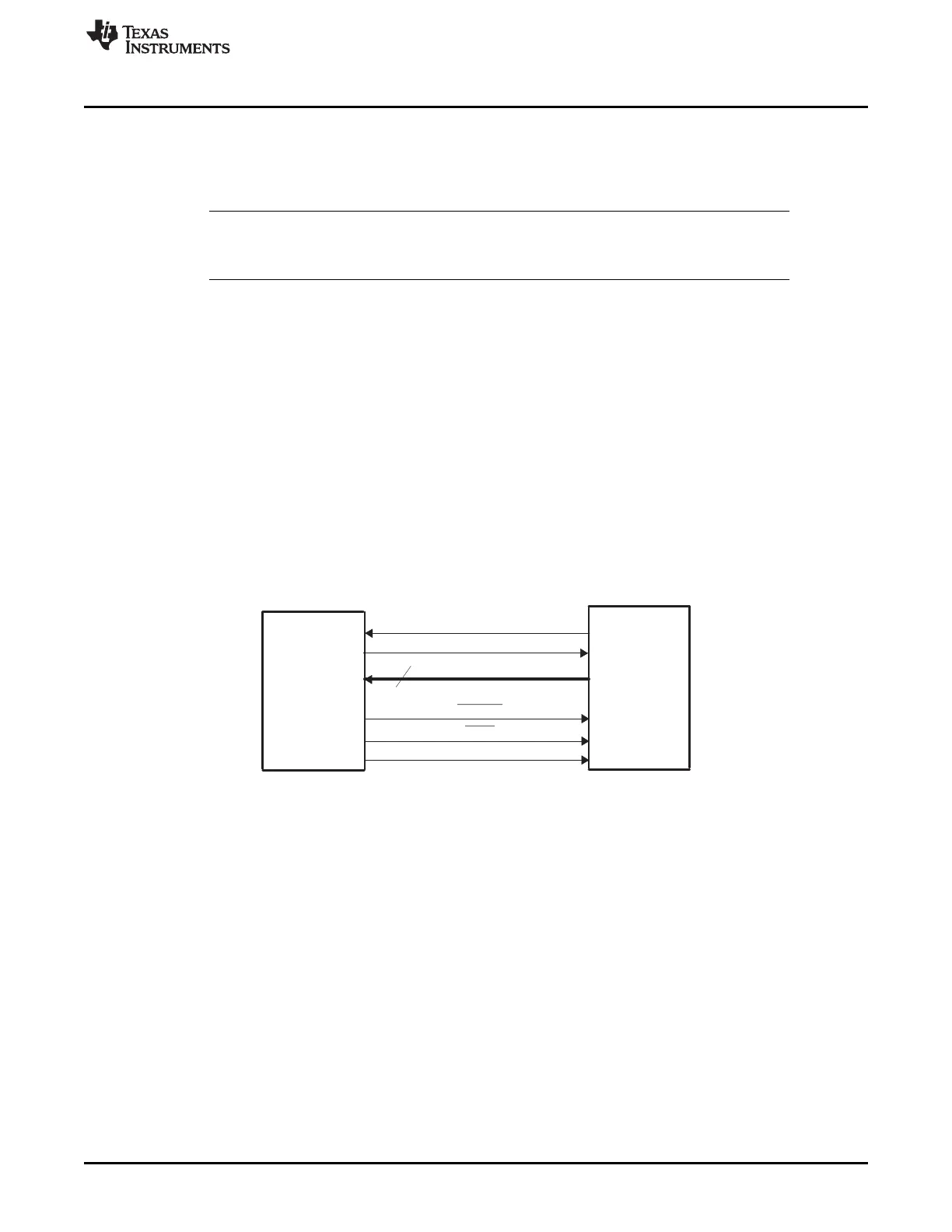
HostControl-GPIO13
Data-XD[15:0]
XZCS6
XRD
DSP
Host
(Dataand
Program
Source)
DSP Control-GPIO12
XA
16
www.ti.com
Bootloader Features
197
SPRUI07–March 2020
Submit Documentation Feedback
Copyright © 2020, Texas Instruments Incorporated
Boot ROM
2.2.19 XINTF_Parallel_Boot Function
The parallel general purpose I/O (GPIO) boot mode asynchronously transfers code from XD[15:0] to
internal memory. Each value can be 16 bits or 8 bits long and follows the same data flow as outlined in
Section 2.2.10. The each word or byte of data is read from address 0x100000 in XINTF zone 6.
NOTE: This mode loads a stream of data into the SARAM of the device using XINTF resources. If
you instead want to configure and jump to the XINTF then use the "Jump to XINTF x16" or
"Jump to XINTF x32" boot mode.
The parallel XINTF loader uses following pins:
• Data on XD[15:0] or XD[7:0]
• 28x Control on GPIO13
• Host Control on GPIO12
The 28x communicates with the external host device by polling/driving the GPIO13 and GPIO12 lines. The
handshake protocol shown in Figure 2-19 must be used to successfully transfer each word via XD[15:0].
This protocol is very robust and allows for a slower or faster host to communicate with the device.
If the 8-bit mode is selected, two consecutive 8-bit words are read to form a single 16-bit word. The most
significant byte (MSB) is read first followed by the least significant byte (LSB). In this case, data is read
from the lower eight lines of XD[7:0] ignoring the higher byte.
The device first signals the host that the device is ready to begin data transfer by pulling the GPIO12 pin
low. The host load then initiates the data transfer by pulling the GPIO13 pin low. The complete protocol is
shown in Figure 2-24.
Figure 2-24. Overview of the Parallel XINTF Boot Loader Operation
The device communicates with the external host device by polling/driving the GPIO13 and GPIO12 lines.
The handshake protocol shown below must be used to successfully transfer each word via the first
address location within XINTF zone 6. This protocol is very robust and allows for a slower or faster host to
communicate with the device.
If the 8-bit mode is selected, two consecutive 8-bit words are read to form a single 16-bit word. The most
significant byte (MSB) is read first followed by the least significant byte (LSB). In this case, data is read
from the lower eight lines of XD[7:0] ignoring the higher byte.
To begin the transfer, the device will use the default XINTF timing for zone 6. This is the maximum wait
states, slowest XINTF timing available. That is:
1. XTIMCLK = ½ SYSCLKOUT
2. XCLKOUT = ½ XTIMCLK
3. XRDLEAD = XWRLEAD = 3
4. XRDACTIVE = XWRACTIVE = 7
5. XRDTRAIL = XWRACTIVE = 3
6. XSIZE = 3 for 16-bit wide
7. X2TIMING = 1. Timing values are 2:1.
8. USEREADY = 1, READYMODE = 1 (XREADY sampled asynchronous mode)
 Loading...