T
pwm
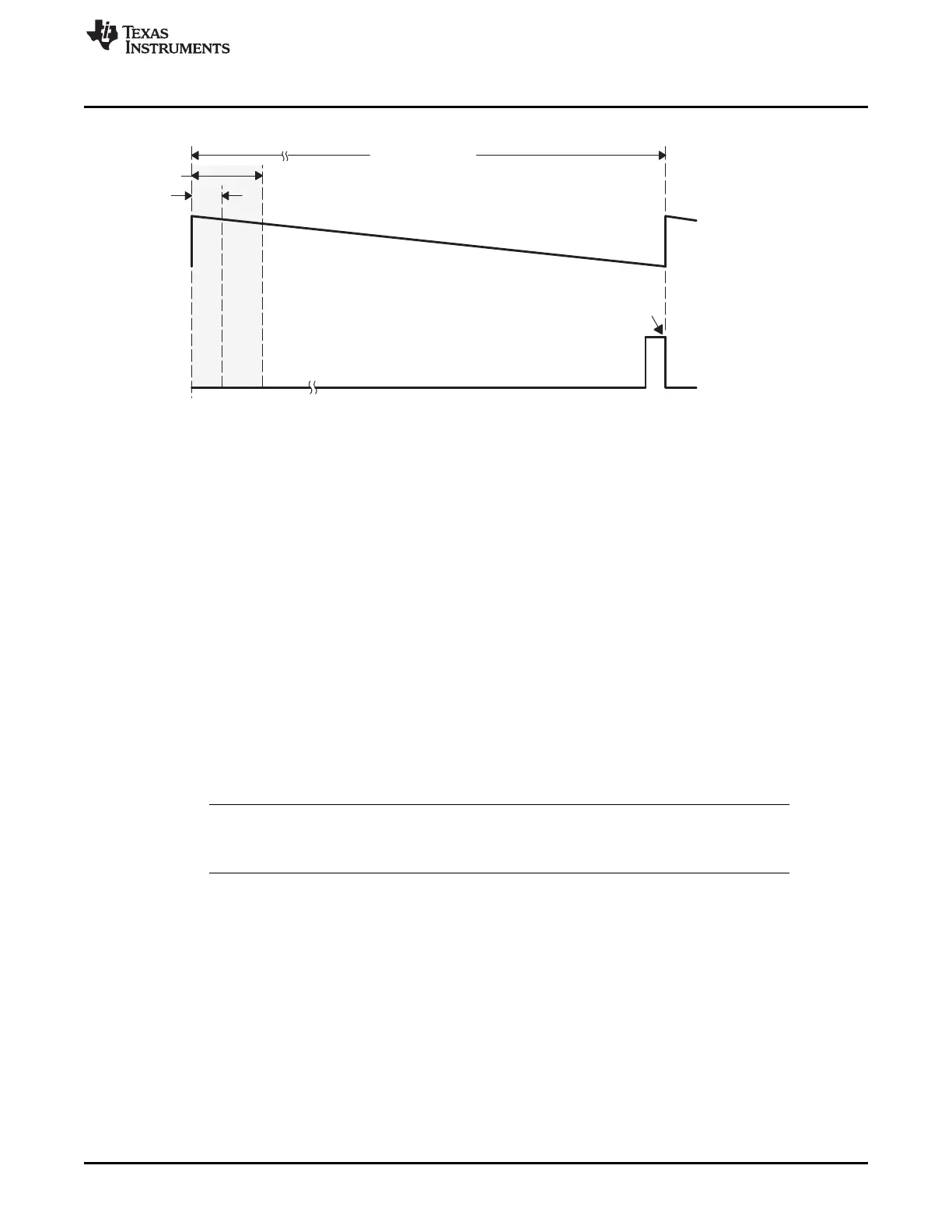
= 1000 ns
EPWM1A
0
100
60 ns
30 ns
(F
pwm
= 1 MHz)
3 6
SYSCLKOUT = 100 MHz
www.ti.com
Operational Description of HRPWM
335
SPRUI07–March 2020
Submit Documentation Feedback
Copyright © 2020, Texas Instruments Incorporated
High-Resolution Pulse Width Modulator (HRPWM)
Figure 4-7. High % Duty Cycle Range Limitation Example when PWM Frequency = 1 MHz
4.2.4 Scale Factor Optimizing Software (SFO)
The micro edge positioner (MEP) logic is capable of placing an edge in one of 255 discrete time steps. As
previously mentioned, the size of these steps is on the order of 150 ps (see device-specific data sheet for
typical MEP step size on your device). The MEP step size varies based on worst-case process
parameters, operating temperature, and voltage. MEP step size increases with decreasing voltage and
increasing temperature and decreases with increasing voltage and decreasing temperature. Applications
that use the HRPWM feature should use the TI-supplied MEP scale factor optimizer (SFO) software
function. The SFO function helps to dynamically determine the number of MEP steps per SYSCLKOUT
period while the HRPWM is in operation.
To utilize the MEP capabilities effectively during the Q15 duty to [CMPA:CMPAHR] mapping function (see
Section 4.2.3.2), the correct value for the MEP scaling factor (MEP_ScaleFactor) needs to be known by
the software. To accomplish this, each HRPWM module has built in self-check and diagnostics capabilities
that can be used to determine the optimum MEP_ScaleFactor value for any operating condition. TI
provides a C-callable library containing two SFO functions that utilize this hardware and determines the
optimum MEP_ScaleFactor. As such, MEP Control and Diagnostics registers are reserved for TI use.
Currently, there are two released versions of the SFO library - SFO_TI_Build.lib and SFO_TI_Build_V5.lib.
Versions 2, 3, and 4 were TI Internal only. A detailed description of the SFO_TI_Build.lib software
functions follows below.
NOTE: Information on the SFO_TI_Build_V5.lib software functions, which support up to 16 HRPWM
channels, can be found in , along with a high-level comparison table between the two library
versions.
Table 4-6 provides functional descriptions of the two SFO library routines in SFO_TI_Build.lib.
 Loading...