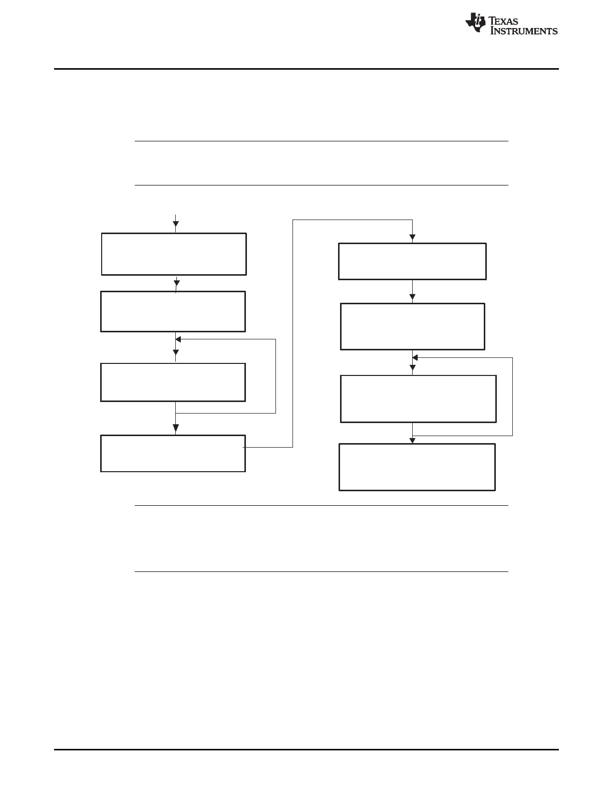
Normal mode
(CCR = 0)
(CCE = 0)
Configuration mode requested
(CCR = 1)
(CCE = 0)
Wait for configuration mode
(CCR = 1)
(CCE = 0)
CCE = 0
Configuration mode active
(CCR = 1)
(CCE = 1)
Changing of bit timing
parameters enabled
Normal mode requested
(CCR = 0)
CCE = 1
Wait for normal mode
(CCR = 0)
(CCE = 1)
CCE = 1
Initialization complete
Normal mode
eCAN Configuration
www.ti.com
788
SPRUI07–March 2020
Submit Documentation Feedback
Copyright © 2020, Texas Instruments Incorporated
Controller Area Network (CAN)
• In order to modify the global acceptance mask register (CANGAM) and the two local acceptance mask
registers [LAM(0) and LAM(3)], the CAN module also must be set in the initialization mode.
• The module is activated again by programming CCR(CANMC.12) = 0.
• After hardware reset, the initialization mode is active.
NOTE: If the CANBTC register is programmed with a zero value, or left with the initial value, the
CAN module never leaves the initialization mode, that is CCE (CANES.4) bit remains at 1
when clearing the CCR bit.
Figure 13-6. Initialization Sequence
NOTE: The transition between initialization mode and normal mode and vice-versa is performed in
synchronization with the CAN network. That is, the CAN controller waits until it detects a bus
idle sequence (= 11 recessive bits) before it changes the mode. In the event of a stuck-to-
dominant bus error, the CAN controller cannot detect a bus-idle condition and therefore is
unable to perform a mode transition.
13.7.1.1 CAN Bit-Timing Configuration
The CAN protocol specification partitions the nominal bit time into four different time segments:
SYNC_SEG: This part of bit time is used to synchronize the various nodes on the bus. An edge is
expected to lie within this segment. This segment is always 1 TIME QUANTUM (TQ).
PROP_SEG: This part of the bit time is used to compensate for the physical delay times within the
network. It is twice the sum of the signal’s propagation ‘time on the bus line, the input comparator delay,
and the output driver delay. This segment is programmable from 1 to 8 TIME QUANTA (TQ).
PHASE_SEG1: This phase is used to compensate for positive edge phase error. This segment is
programmable from 1 to 8 TIME QUANTA (TQ) and can be lengthened by resynchronization.
PHASE_SEG2: This phase is used to compensate for negative edge phase error. This segment is
programmable from 2 to 8 TIME QUANTA (TQ) and can be shortened by resynchronization.
 Loading...